• The move to the new server is done. There are some software and database maintenance updates in process. This has us passing the hat around to help out. We appreciate any donations. Seriously, even a dollar helps. The payment page may be found here - https://www.audiokarma.org/support.html

How lucky can a guy get?

Transistors

Show on left is original Toshiba 2SD424, right what came with the unit and bottom bogus.
The top two test good in all ways and the bottom bogus one has the right voltage also but fails diode test.
Is it possible that the output on the right side is a real Toshiba?
The unit came with 8 of them.
Peter

It's possible, but I don't think so, see the small size of the cutout? Also the silk screening of the logo is wrong, also, see how the "cap" is not centered on the "base"?
Counterfeiters are like pirates, deserve to be shot.
Casey
 
me thinks that unit was shot at and missed, then shat at and hit. then pizzed on all over....

I have jumped on similar projects in the past, but starting to learn better, just have too many projects and too little time....

kudos for the effort to this point, and good luck!
 
Sounds like a typical original 9090db

Now got $52.99 into it...heatsink compound, ($2.99) just sucked the transistors in. Now I understand why they might go bad, (because the factory heat transfer compound is at the end of its life after 30+ years), and probably any 30 year output should have the stuff replaced as a PM. I put on just enough so that when tightened down a very small bead of white compound pressed out.
Three of the outputs came with the unit and the other five came from a back up set of 5 outputs, hate to use them but this unit really does deserve original Toshiba’s.
The restringing dial cord job is easy when following the manual.
The original tuner which is in another unit is connected to MAIN to drive this one, sounds typical 9090db before a re-cap.
Sending Merrylander a case for evaluation and re-veneering soon, this unit will need a case in about 2 months.
 

Attachments

  • STA72663.jpg
    STA72663.jpg
    49.3 KB · Views: 55
  • STA72671.jpg
    STA72671.jpg
    86 KB · Views: 69
I have the same type of problem with an otherwise whole and functional QRX 7001 that I want to recap. In my case its the function selector switch shaft. Did your replacement shaft come from a Sansui unit also, or ??

Thanks for the tip.
 
I love seeing the dead resurrected again! Gives me hope with the 'Sui's I've got sitting DOA right now.

Keep us posted, Peter! :thmbsp:

:lurk:
 
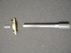
The fabricated speaker switch shaft was made from a 9090db selector shaft. If the QRX 7001 is similarly configured replacement is pretty easy, just remove the face plate and remove the 2 screws that hold the shaft bracket. The switch shaft can then be removed out of the receiver. There are 2 retaining snap clips that hold the shaft to the bracket; just R&R. Shown is what is left of my donor selector shaft.
Try Barter town someone might have a replacement.
 

Attachments

  • STA72674.jpg
    STA72674.jpg
    95.9 KB · Views: 52
the Shaft

I have the same type of problem with an otherwise whole and functional QRX 7001 that I want to recap. In my case its the function selector switch shaft. Did your replacement shaft come from a Sansui unit also, or ??

Thanks for the tip.

If you want to send me your bad shaft I will see if either I can fix it or match/rework one of the spare 9090 shafts I have out in the shop.
Casey
 
Lots of punch/drive

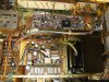
Just about got this one all cleaned up, when I finally put the shop vac on blow very little came out of the chassis.
The selector shaft needs to be pushed back into position; there is no change no matter what position it’s at.
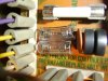
Installed two 1.5A and one 1.0A fuse, just cut a notch in some tubing for the lead protection and stripped some wire for the lead itself.
Even though this unit re-cap job is not complete the caps that have been replace made a dramatic difference in bottom end, has some real punch now, will order the other caps soon. I use 3 or 4 dabs of mirror adhesive on the bottom of the larger caps for stability.
The 2 small heatsinks cleaned up with a wire brush and a leaf paint pen.
The driver circuit board is out of another unit so still need to rebuild it and the tuner needs to be gone over, both jobs take a bit of time.
Other than the needed caps and resistors the only thing missing is 4 screws for the heat sink and a full set of screws for the bottom cover.
 

Attachments

  • STA72690.jpg
    STA72690.jpg
    129.9 KB · Views: 102
  • STA72685.jpg
    STA72685.jpg
    63.8 KB · Views: 90
  • STA72682.jpg
    STA72682.jpg
    99.6 KB · Views: 76
  • STA72678.jpg
    STA72678.jpg
    75 KB · Views: 83
  • STA72677.jpg
    STA72677.jpg
    107.9 KB · Views: 85
Oh and yes after installing the tuner and hooking it up, NO SOUND, just took me 15 minutes to figure out the jumpers were missing HaHa, not the first time.
Peter
 
The diodes on the power board cleaned up nicely! That chassis anodizing looks very gold from the pictures, I've never had one that bright, usually it's more of a plain tan color.
 
naderpe,

I'm in Oak Park and will be doing my dad's 9090db as soon as I get the guts... I have the maintenance manuals also.

For what it's worth, let me know if I can help. For one thing, I can provide a third hand at some point.... I need something to get me off my butt and into the cabinet.
 
It must have been in a smoke free environment for sure, to remove the Sansui glue I use a 4” screwdriver, (dull knife sharpened) and apply steady pressure to push the glue. The most important part is the angle of the screwdriver; I keep the angle small as possible to the board, not 90 degrees.
The 2 large caps had the lead holes enlarge with a .038” drill, the Muse UKZ 470uF 50V have .030” wire leads and will not pass thru the holes otherwise.
 
With its own parts now

TR05, TR01, TR03 and R11 were toast on the driver board. All replaced and the board recapped.
The unit has incredible power punch and clarity from this unit with the original boards now.
 

Attachments

  • STA72701.jpg
    STA72701.jpg
    111.2 KB · Views: 65
Excellent work (so far)! It's really nice to see one of these fine old receivers being brought back to life and a state of "good health", especially one that has had such a "near death experience". No doubt when you are finished with it, and the case is done, it will be a gleaming treasure that will look and sound like a "jillion" bucks! Please keep the updates coming; it is inspiring to the rest of us!
 
Back
Top Bottom