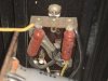
• The move to the new server is done. There are some software and database maintenance updates in process. This has us passing the hat around to help out. We appreciate any donations. Seriously, even a dollar helps. The payment page may be found here - https://www.audiokarma.org/support.html

How to adjust the current bias in Kenwood KR-6160 receiver

dlucy

dlucy67 (Doug)
Staff member
Moderator
Subscriber
In a current thread, some of our resident Kenwood experts chime in on where to measure the voltage across emitter resistors in order to calculate the current bias... so you can then adjust a trimpot to bring the current bias up or down to factory spec.

I have the "Kenwood Audio Adjustment" PDF, so I can see the example procedure and the specific current my receiver, a KR-6160, is supposed to be adjusted to... but my schematic is a bit different from the example and I have two emitter resistors per channel instead of just one.

I need someone like @hopjohn to explain where I should be measuring and whether I'm aiming for the target current bias from the chart OR half of that.

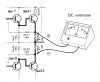
Screen shots from the Kenwood Audio Adjustment PDF:
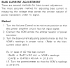
Adjust bias 01.png

Adjust bias 02.png

The chart in this PDF says the KR-6160 should be adjusted to 20mA.

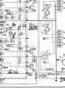
This is the schematic for the power amp stage in the KR-6160:
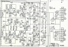
Adjust bias 03.png

So, where should I be putting my voltmeter leads and reading the voltage? Taking just one channel, I think there are two emitter resistors: R171 and R172, each a high wattage 0.47 ohm resistor coming immediately after the final output transistor's emitter.

A. Put the voltmeter leads one on one leg of R171 and the other lead on the other leg of R171 and take a the measurement? If so, am I aiming to adjust this channel's current bias trimpot to reach the 0.47 ohm X 20ma = 9.4mVDC? or just half of that, 4.7mVDC?

B. Put the voltmeter leads one on the leg of R171 closest to Q1 and the other lead on the leg of R172 furthest away from Q2 to take a the measurement? If so, I should adjust this channel's current bias trimpot to reach the 0.47 ohm X 20ma = 9.4mVDC, right?

C. Something else.

Thanks for the help!
 
Last edited:
Register to hide this ad
Measure across R171 for the left channel, R271 for the right.

Awesome. Thanks! Now I know what to do this time for this model.

Will you explain why? So I know what to do next time? Is it "measure the voltage across the emitter resistor headed out to the output capacitor"?

You're aiming for 9.4mV, not 9.4V (20mA x 0.47 = 9.4mV)

Doh! Thanks! I've updated my prior post to read as mV instead of V.
 
Last edited:
measure the voltage across the emitter resistor headed out to the output capacitor
Well yes, that's it basically. It is capacitor coupled output, but more to the point is that this is a quasi complimentary type topology ( 2 NPN output Qs in the left channel, 2 NPN in the right) so there's just one emitter resistor per channel to measure across.

Interestingly the schematic says the nominal collector current is 5-100mA, I've never understood why Kenwood put these large range figures there with some amps/receivers as it's not very useful in setting the bias. It's good that you found further documentation pointing to the 20mA figure to narrow it down.
 
Well yes, that's it basically. It is capacitor coupled output, but more to the point is that this is a quasi complimentary type topology ( 2 NPN output Qs in the left channel, 2 NPN in the right) so there's just one emitter resistor per channel to measure across.

Awesome. Thanks! Exactly what I was looking for.

Interestingly the schematic says the nominal collector current is 5-100mA, I've never understood why Kenwood put these large range figures there with some amps/receivers as it's not very useful in setting the bias. It's good that you found further documentation pointing to the 20mA figure to narrow it down.

Yep, I'm just using the Kenwood document that covers many models from the AK Database.

http://akdatabase.com/AKview/albums/userpics/10007/Kenwood Audio Adjustment.pdf

Maybe we could update that to include an image of a quasi-complementary design and showing you only measure across the final emitter resistors.
 
@hopjohn I'vet looked for a similar model so I can test my understanding of your answer. Will you verify I'm applying this correctly?

The Kenwood KR-5150 receiver schematic is drawn a little differently than the KR-6160 schematic above:

Kenwood KR-5150 power amp closeup.jpg

So, in this KR-5150 quasi-comp design (two NPN's per channel) the emitter resistor is the resistor that connects on of the transistors' emitters to the output path, in this case the output cap at C271. So, of the two output transistors in this channel, Q3 and Q4, only Q4 has an emitter resistor in the path to the output cap, so resistor Re92 is the one to measure?
 
Yessir, if we are talking about this channel only you'd measure across Re92 at the two pins (picture is too small to read the pin numbers accurately).
This one however would be 30mA x 0.47 Ohm = 14.1mV
 
So, here is where to measure and adjust the current bias in the Kenwood KR-6160 receiver:

View attachment 1125412
Hi Doug,
Thanks for all of your contributions on AK! I’m actually using another one of your threads to help me restore my Harman Kardon 730 Twin.

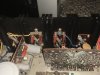
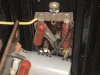
As for the Kenwood KR-6160, where exactly are the resistors in question here? There’s no silkscreened PCB here, so I assume the .47ohm resistors on the right side of each output transistors are what I am supposed to be measuring across? I tried measuring DCmV, but my multimeter is giving me a reading of 0. This is one of the older units that I (a novice) have worked on, so I’d hate to make any assumptions here. Thanks in advance!
 

Attachments

  • image.jpg
    image.jpg
    151.7 KB · Views: 54
Last edited:
There are two 0.47 ohm resistors in each channel, directly soldered to the output transistors. You want to measure the correct one on each side, so figure out where Q1 and Q4 are on the heat sink, figure out which pin of the transistors is the emitter, then select the resistor soldered to their emitters.
 

Attachments

  • BD995734-F635-4B9A-907F-CA524796D530.jpeg
    BD995734-F635-4B9A-907F-CA524796D530.jpeg
    122 KB · Views: 95
  • AA3E4B64-7E4E-4A1B-96DA-32A3096218A9.jpeg
    AA3E4B64-7E4E-4A1B-96DA-32A3096218A9.jpeg
    79 KB · Views: 89
  • 9B896675-9D85-4561-B14D-6F36E88B5AB4.jpeg
    9B896675-9D85-4561-B14D-6F36E88B5AB4.jpeg
    115.7 KB · Views: 82
  • 7CC71533-D20D-4CBC-9057-A1AAE8BEF0CB.jpeg
    7CC71533-D20D-4CBC-9057-A1AAE8BEF0CB.jpeg
    98.7 KB · Views: 80
Hi dlucy I have rebuilt my 6160 amp board. But just going over setting the bias and stuff I find odd voltages at the collectors of the outputs.
Q1 89v. Q2 21v. Q3 44v. Q4 89v.
Does this seem normal q2 is only getting 22v at the collector. I was able to set bias at 9.4mv

And it sounds really good and balanced to me it has been about two months since I rebuilt the board and everything seems normal except that low voltage at q2.
 
Does this seem normal q2 is only getting 22v at the collector.

Might want to "name-check" @dlucy and probably @hopjohn as well.

Me, I'm just passing through, but it sure looks to me like the idle current adjustment would not only affect the center voltage, but would also affect the signal gain of the power amp! I wonder what I'm missing?

Edit: Ah, now I see the "NF" connection, which presumably stabilizes signal gain.
 
Last edited:
Hi. And thanks Chazix. Can you explain. Since I got this amp. I noticed weird voltages. On my pioneer sx1500td you can actually adjust the center voltage with a potentiometer. But in this kenwood what would influence that to be off by 20v???
 
But in this kenwood what would influence that to be off by 20v???

I'm afraid I really don't have a good idea about that. I was hoping that one of the other contributors who have had (relatively!) recent experience with this model would chime in. My curiosity was piqued by my impression that adjusting the idle current would also affect the center voltage, but the more I look at the partial circuit above, the more I think that I am still missing some important features.
 
Hello and thanks again. I was messing with this receiver last night. And I noticed adjusting the bias would also influence the center voltage at q2 and q3. So I was able to bring the voltage up to 43v on both transistors now the small issue is idle current is very low after doing so. The only thing I’m afraid is stv-3 being shot. That particular channel had both outputs ,drivers and a few resistors burnt.
So I’m getting back to it see if I can adjust both channels a little better. Thanks for your help and advice. ;)
 
The only thing I’m afraid is stv-3 being shot.

Well, I at least found a schematic that would show me the STV-3. That's one thing I was definitely missing. (Still a pretty miserable schematic to follow, though.)

I think if this was on my bench I would set the bias correctly on both channels and then measure the voltage across the STV-3 in either channel, with a precision of tens of millivolts or better.

If it turned out that the STV-3 voltage was higher on the channel where the drivers etc. had been replaced, I would suspect that there was still something wrong in the last two stages, perhaps the replacement transistors having Vbe too high or Hfe too low to work appropriately in this circuit.

If it turned out that both channels' STV-3 voltages were close to each other, then I would suspect that something was wrong with the circuitry close to Qe5, but I don't have a suggestion what that might be.
 
:confused::confused:Hi. After switching and moving things around(transistors) I replaced a few more resistors. Move transistors from left to right channel even the outputs from left to right with no effect in n behavior. After a couple of hours of scratching my head I decided to move the stv’s from left to right and bingo.... bias and center voltage changed bias started stabilizing as the unit warmed up , prior to doing this bias would only jump to about 1.8mv on the left channel and about 9.2mv on the right channel and that was after about 15-20 minutes idling at the correct center voltage. So I’m borrowing stv-3 from my old pioneer and doing some more testing. Let me mention before I even noticed the off center voltage I was able to adjust bias symmetrically but center voltage was way off at about 20vdc between channels and also discovered r27 2.2k resistor a little toasty, weird thing the unit sounded good for long periods of time playing in my living room

I have tried making my own stv-3 before when I was working in my jvc vn900 with out success using a variety of different diodes, all the ones mentioned in this site. unlike the double diode varistors found in many units like my sansui 9090db and many marantz units this triple diode varistors stv3 is one that I fear :confused:
I will report my findings after replacing stv3
Thanks again for your contributions
 
:confused::confused:Hi. After switching and moving things around(transistors) I replaced a few more resistors. Move transistors from left to right channel even the outputs from left to right with no effect in n behavior. After a couple of hours of scratching my head I decided to move the stv’s from left to right and bingo.... bias and center voltage changed bias started stabilizing as the unit warmed up , prior to doing this bias would only jump to about 1.8mv on the left channel and about 9.2mv on the right channel and that was after about 15-20 minutes idling at the correct center voltage. So I’m borrowing stv-3 from my old pioneer and doing some more testing. Let me mention before I even noticed the off center voltage I was able to adjust bias symmetrically but center voltage was way off at about 20vdc between channels and also discovered r27 2.2k resistor a little toasty, weird thing the unit sounded good for long periods of time playing in my living room

I have tried making my own stv-3 before when I was working in my jvc vn900 with out success using a variety of different diodes, all the ones mentioned in this site. unlike the double diode varistors found in many units like my sansui 9090db and many marantz units this triple diode varistors stv3 is one that I fear :confused:
I will report my findings after replacing stv3
Thanks again for your contributions
 
:banana::banana:So. After a lovely evening sitting in front of my 6160. My conclusion is...... bad stv-3. After replacing the bad stv bias and center voltage are near perfectly matching on both channels. After playing Christmas music on the fm section for about an hour, turn the music off, switched to aux input, remove speakers and measure bias at 9.6mv and 9.2mv and center voltage near identical as well . One thing to mention I had used ztx696b at q5 and q6 but as I was troubleshooting this thing I removed ztx696b and replaced them with the old original to39 cased 2sc627 which I feel generate much heat So I feel the smaller To-92-3 cased ztx696b can’t disipate heat as well as the original To39 2sc627 which originally had a heat sink mounted on its body. So. My question. What would be a good substitute in a different case that would be suitable for q5 and q6 in this application. Thanks in advance :banana:
 
Last edited:
Back
Top Bottom