• The move to the new server is done. There are some software and database maintenance updates in process. This has us passing the hat around to help out. We appreciate any donations. Seriously, even a dollar helps. The payment page may be found here - https://www.audiokarma.org/support.html

How to bypass tone controls without a schematic?

Nick_the_'Nole

Super Member
I dug out my little Magnavox EL84-SE today to check on the values for new coupling capacitors, and while I was pondering it I decided once and for all I want to remove the tone controls from it. I'll leave the volume pot there, but I'd like to get rid of the bass, treble and balance pots.

I know a lot of people do such a thing to these amps, but not having a schematic to it and not seeing any readable values on the pots themselves, I don't know what's safe to just take out or what needs to be replaced with fixed resistors. (And for that matter, what values of fixed resistors.)

Can somebody who's redone one of these things please give me some pointers?
 
Register to hide this ad
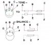
Well if you have an ohmmeter, measure the resistance with the control set at the minimum boost/cut (center) from the tap to each end, and find a pair of resistors with similar resistance for each channel of each tone control. There will be four resistors per tone control.

The balance control is different, with the control centered, that should be the maximum resistance with no further increase as the pot is rotated in one direction. Just to be safe, get a resistor of that value and use it.There will be two resistors needed here.

The wipers are wired backwards,so of course full left means no right channel and full right means no left channel, with both channels at max when centered.
without seeing the schematic it will be hard to pick the sides that would probably be grounded.

But when centered there should be only a very low proportionate resistance between one wiper and one of the other two terminals. those are the two to connect together, and they will be opposite of each other on the two sections of the balance pot.
 

Attachments

  • replacement.jpg
    replacement.jpg
    36.5 KB · Views: 97
Last edited:
x tone controls

I sounds like you have a fun project. My Magnavox never sounded right until I removed the tone controls. It is best to find a schematic. If you list the model number of your unit on this site, you may get a lead to the schematic you need.
 
Thanks, Mark, that makes sense, I'll have to hunt down my multimeter tomorrow and check it out. Seems simple enough, though.

Yeah, a schematic would be best, but there's not even a model number on this thing. It's the standard 4-tube Maggie 6BQ5 SE with the 6EU7 driver, so I probably could turn something up if I hunted hard enough, but from what Mark says, it looks like I could do the mods faster than I could find a schematic.
 
An all tube unit... best to do it that way, there could be level shift (gain), circuitry or impedance issues otherwise.
 
markthefixer said:
Well if you have an ohmmeter, measure the resistance with the control set at the minimum boost/cut (center) from the tap to each end, and find a pair of resistors with similar resistance for each channel of each tone control. There will be four resistors per tone control.

The balance control is different, with the control centered, that should be the maximum resistance with no further increase as the pot is rotated in one direction. Just to be safe, get a resistor of that value and use it.There will be two resistors needed here.

The wipers are wired backwards,so of course full left means no right channel and full right means no left channel, with both channels at max when centered.
without seeing the schematic it will be hard to pick the sides that would probably be grounded.

But when centered there should be only a very low proportionate resistance between one wiper and one of the other two terminals. those are the two to connect together, and they will be opposite of each other on the two sections of the balance pot.
The problem with this approach, is that you basically gain no advantage by doing this. The tone control filters are still completely inside the circuit. You just have them permanently centered now. This approach will not yield an appreciable improvement in performance, if that is your goal (which it usually is for this sort of mod).

Admittedly, without a schematic, unless you are willing to completely trace-out your circuit to create your own schematic, you are kind of stuck. But I still don't see any significant advantage to this approach over just keeping your controls centered. So why bother?
 
goldear said:
The problem with this approach, is that you basically gain no advantage by doing this. The tone control filters are still completely inside the circuit. You just have them permanently centered now. This approach will not yield an appreciable improvement in performance, if that is your goal (which it usually is for this sort of mod).

Admittedly, without a schematic, unless you are willing to completely trace-out your circuit to create your own schematic, you are kind of stuck. But I still don't see any significant advantage to this approach over just keeping your controls centered. So why bother?


Well I thought about that, and decided it was his business, and just answered the question.
Yes, the only advantage is the "fiddle factor". And the other way, unless the way has been proved by someone else, is admittedly riskier. A schematic is just the first step, the next would be a signal generator and a scope.
Without a model number, chassis id or something, it's a tracing job, then a guessing / reverse engineering job. not for the faint of heart, and definitely not a "remote control" job as well.
 
One of the biggest problems....

without a schematic is that the designer of this little amp, which I assume came from an old console - right? - was probably under pressure to design with the fewest parts. This means that he/she may well not have used some 'tricks' to get the job done.

I wouldn't make any assumptions if this is the case. In other words, its not going to easy to do it right without the docs.

Cheers,

David
 
markthefixer said:
Well if you have an ohmmeter, measure the resistance with the control set at the minimum boost/cut (center) from the tap to each end, and find a pair of resistors with similar resistance for each channel of each tone control. There will be four resistors per tone control.

I agree with Goldear, this approach, as well intentioned as it may be, will unfortunately in no way provide any benefits than you wouldn't already be getting by just setting the tone/bal controls to their center of rotation.

The idea is to completely remove the tone control circuitry from the audio path. You must either bypass this section completely, or take out the signal at a point just before it enters the tone control section. In/Out stage impedances & levels are other factors that need to be considered if you decide to go either way.

This mod is probably not an easy task without a schematic, but given the relative simplicity of tube circuits, it shouldn't be too difficult to trace and draw your own schematic. Just make sure that you don't leave out any parts of the circuit that might be relevant to the intended modification.

Just my $0.02. Hope that helps a bit.

-Alex
 
Last edited:
Vintageaudio123 said:
I agree with Goldear, this approach, as well intentioned as it may be, will unfortunately in no way provide any benefits than you wouldn't already be getting by just setting the tone/bal controls to their center of rotation.

The idea is to completely remove the tone control circuitry from the audio path. You must either bypass this section completely, or take out the signal at a point just before it enters the tone control section. In/Out stage impedances & levels are other factors that need to be considered if you decide to go either way.

This mod is probably not an easy task without a schematic, but given the relative simplicity of tube circuits, it shouldn't be too difficult to trace and draw your own schematic. Just make sure that you don't leave out any parts of the circuit that might be relevant to the intended modification.

Just my $0.02. Hope that helps a bit.

-Alex

"The idea is to completely remove the tone control circuitry from the audio path. You must either bypass this section completely, or take out the signal at a point just before it enters the tone control section. In/Out stage impedances & levels are other factors that need to be considered if you decide to go either way."

Exactly right. Many times the tone circuit is part of the gain circuit and bypassing it without consideration of what that will do to the over all gain budget of the preamp section will have negitive effects on the preamp. This would be very model specific.

Lefty
 
Since we're starting to get deep here, my first pass for removal AFTER a good schematic has been generated and confirmed would be to look at all the capacitors in the tone control circuits. These are going to be first order rc circuits. Slope predictable. Calculate the effective resistance portion of the reactrance at what is hoped to be the designed 3db point, and replace them one at a time with similar value resistors, checking levels and frequency curves left after each change. When done, theoretically a purely resistive circuit will not impart frequency dependent level or phase changes.

Then IF it works out well, do resistance simplification, i.e. "solve & simplify" the circuit problem like an engineering school practice problem.

BUT this does not take into account any "tricks" done to stabilize the circuits.. some capacitance is a necessary evil.

This would be a real project, as opposed to a whim....

But the original call was for anyone who had done it before. There has been no response on that.
 
Alright, well, I didn't intend for this to turn into a big debate, my main reason for removing the pots is that they're pretty much shot and there is no real "center" on a couple of 'em anymore. And no, Deoxit didn't help. However, I got interested in the idea of pulling the whole tone circuits out if possible, so I did a little closer checking.

The balance control didn't really have much effect in the tone path, so it came out pretty easily with just a resistor to replace it. Removing the bass control only involved clipping crap out rather than replacing anything. It was just two resistors making a low-pass filter off the + of the RCA inputs, which was then run to ground through the pot.

I tried the amp after removing those two, and the sound has definitely changed though I'm not sure exacly how it'll end up once I take care of the coupling caps and such. I daresay, though, that there's already been an improvement with no ill-effects on gain or anything.

The treble control, though... that's gonna be a little more involved. This is where I'd really like some advice from someone who's modded one of these amps before. The issue here is that it isn't going to be an easy circuit to trace without a schematic, being tied into the volume control which looks absurdly complicated. A related question: WTF is this thing on the volume control, looks like a ceramic disc capacitor but is rectangular and has 5 leads coming out of it? I've never seen something like that before...
 
Nick_the_'Nole said:
A related question: WTF is this thing on the volume control, looks like a ceramic disc capacitor but is rectangular and has 5 leads coming out of it? I've never seen something like that before...

Its probably a hybrid circuit, with caps and resistors related to the contour circuit (loudness compensation), encased in a single ceramic chip for thermal and electrical stability. That also insures consistency in the manufacturing process.

My Fisher X-202-B also uses them on the tone controls, hi filter, and at the first input stage (phono, mic, mag) feedback loops.

-Alex
 
Do you have anything else in the signal chain that does loudness compensation?
If not, considering the presence of that hybrid, I would just replace the worn out treble control with the resistors.
 
Well, I honestly can't tell at this point... The volume control is covered in caps and resistors in addition to that hybrid, and being unable to see exactly what they all hook to I really don't know what they all do. I suppose with a multimeter and some scratch paper I could try to make sense of it, but I've got a lot of other projects to tend to before getting too deeply involved in this. Agreed, the fixed resistors are looking like a better option at this point.

Then again, if I do in the future get ambitious (or bored) enough to try tracing all the crap in the loudness compensation, would it possibly be easier to just pull all that crap out and start over through the entire signal path? It should be a pretty simple and common circuit design, no?
 
Sorry , I didn't express myself clearly, I meant any other piece of equipment, not stuff within the chassis of the unit in question.
 
Now hold on... can it really be this simple?

I still don't know what all that stuff is in the volume and treble controls. But, I found the wires going from the inputs to the treble control, which is subsequently connected to the volume control, and then I found the wires going from the volume control to the 6EU7. Now, unless I'm misunderstanding the schematics I've found for similar amps, couldn't I just cut all that extra mess out and replace it with a simple 1meg or so dual-gang pot in between the inputs and the driver tube? That should theoretically remove all tone filters but still give me a volume control, right?
 
Sounds reasonable... there will be no "loudness" compensation for the various volume levels (IF there ever was...) .

What is the value of the current volume control?

Also not to confuse the issue, but the volume control probably has an "audio" or logarithmic taper... That just means that there isn't a linear relationship between the wipers position and the resistance (or voltage drop if one end is grounded) read between either end. In other words a 100k ohm linear taper pot would have 50k measured to either end of the pot in the middle. The audio taper would have some other values.

A linear taper pot crowds the volume adjustment range together a bit, it can get annoying, those nice little marks on the panel wouldn't correspond any longer.

That said, I have a 100k ohm dual volume control from a pioneer sx-550 at my elbow. it has the "loudness" tap, but the tap can be ignored. It is a pc board mount version BUT it has a threaded shaft (and nut!) for panel mounting.
It has NO detents, it is a smooth adjustment range (some controls I have seen, mainly tone controls, have detents.)
 
From my understanding, it's possible to tie a resistor in front of a linear pot and get a pretty good facsimile of a log taper, possibly even better than the commercial logarithmic pot that's already in there. I dunno, I'll play around with some pots and resistors out of my junk box, see what happens. The loudness pot that's in there now looks to be a 3.3 meg, though I'm not sure exactly how it works in conjunction with the 1 meg treble pot, so I figured a 1 meg volume pot as a replacement would be a good starting value to work with.

I'm not sure I'm clear yet, what does "loudness compensation" do? Rather, why would it be desirable instead of just a straight volume control?
 
"I'm not sure I'm clear yet, what does "loudness compensation" do? Rather, why would it be desirable instead of just a straight volume control?"

You can think of loudness as an automatic tone control that adds more bass and treble as the volume control is lowered. Most loudness circuits are just switch actuated using a tap off the main volume control, but Yamaha, for one, used a unique loudness pot that could adjust the amount of loudness independently of the volume setting. The circuits can be somewhat complex but many models would publish the loudness compensation curves in their owners manuals and a picture is worth a thousand words in showing the effect of the loudness circuit.

Lefty
 
Back
Top Bottom