• The move to the new server is done. There are some software and database maintenance updates in process. This has us passing the hat around to help out. We appreciate any donations. Seriously, even a dollar helps. The payment page may be found here - https://www.audiokarma.org/support.html

I got an old mono tuner, best method of wiring up antenna?p

saabracer23

AK Subscriber
Subscriber
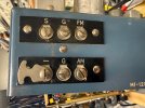
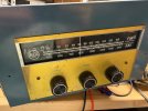
That will make me seem like a complete noob, and in this case I pretty much am. I have this old AM/FM tube receiver, mono of course. I want to see how well it receives both AM and FM and I’m curious how to best hook up in 10 to this. For the FM do I hook one wire to the screw labeled FM and the other wire labeled G or S? What about a.m. do I use that little latch to connect the “-“ and G? Wire a standard AM loop antenna to the AM and G with the latch not latched?
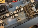
IMG_2771.jpeg
IMG_2772.jpeg
IMG_2773.jpeg


Dan
 
Register to hide this ad
on the AM side, the - and G need the jumper if its a single wire. If its a dipole or a loop, usually you want the AM and the - terminals, and G goes to ground. You can ohm check that to confirm, whichever reads to chassis gets the ground wire, the one that reads to AM is the other end of the antenna coil. Can try it with or without the jumper, use whichever works better.

You can skip the ground connection too if you want.

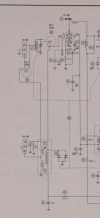
FM I'm not sure. Normally 3 terminals are what you get with a 75 and a 300 ohm input. Wild guess, G is ground and would be the shield for a 75 ohm coax, and S to FM would be what you use for 300 ohm. Schematic may be a clue, whichever goes to chassis directly would be the shield of the coax, the one that goes to each end of the coil is 300 ohm, the roughly-center tap or whatever runs right to the FM tuner would be the center conductor of a 75 ohm.

or just connect one lead to FM and see what works best for the other lead.
 
on the AM side, the - and G need the jumper if its a single wire. If its a dipole or a loop, usually you want the AM and the - terminals, and G goes to ground. You can ohm check that to confirm, whichever reads to chassis gets the ground wire, the one that reads to AM is the other end of the antenna coil. Can try it with or without the jumper, use whichever works better.

You can skip the ground connection too if you want.

FM I'm not sure. Normally 3 terminals are what you get with a 75 and a 300 ohm input. Wild guess, G is ground and would be the shield for a 75 ohm coax, and S to FM would be what you use for 300 ohm. Schematic may be a clue, whichever goes to chassis directly would be the shield of the coax, the one that goes to each end of the coil is 300 ohm, the roughly-center tap or whatever runs right to the FM tuner would be the center conductor of a 75 ohm.

or just connect one lead to FM and see what works best for the other lead.
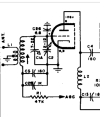
Looks like what you say makes perfect sense. I haven’t thought about it in the same way as the coax and shield.

IMG_2783.png

Dan
 
yeah thats weird. Its not what I was expecting to see. I was figuring on something more like this

1781528748227.png

Thats a Sherwood S3000 but its a reasonably typical arrangement. 300 ohm balanced from end to end, 75 ohm unbalanced from ground to either end.

Looks like its meant for an unbalanced input only but not entirely sure what the switch is about. Unless the idea is to connect a single wire and it just switches between FM and AM?
 
Looks like its meant for an unbalanced input only but not entirely sure what the switch is about. Unless the idea is to connect a single wire and it just switches between FM and AM?
To use the FM antenna for AM too. Most Philips tube radios have similar arrangement at the antenna banana sockets. A short selects the various configurations.

What is the model number of this tuner? The schematic looks like a Photofart... euh... Photofact version.
 
Back
Top Bottom