• The move to the new server is done. There are some software and database maintenance updates in process. This has us passing the hat around to help out. We appreciate any donations. Seriously, even a dollar helps. The payment page may be found here - https://www.audiokarma.org/support.html

IBBA in Sherwood S-5000 II

gvocale

Active Member
I am trying to install an IBBA board into a Sherwood S-5000 II

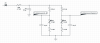
I am using the following schematic, posted here on AK in another thread.

If I measure resistance between the DC balance pot and ground, with the IBBA not plugged into the amp, by turning the potentiometer I swing between 15k ohms and 25k ohms. It makes sense to me, as it is a 15k resistor + 10k bias potentiometer.

I connect the IBBA ground to the chassis ground, and the header supply to the negative rectifier source. Now I measure a swing between 6k ohms and 7k ohms.

What is happening? Why my resistance is off?

My IBBA at A / B / C / D gives me just -11, down from -30v at the header supply, rather then the 18~21.5v I would have got if the resistance would have measured 15k to 25k.

Fisher 500c IBBA Bias Modification.jpg
 
Last edited:
Register to hide this ad
probably reading across whatever else is in the bias supply. Is this just currently wired to the bias voltage source and ground, with the A-D connections going nowhere for testing?

THis is the board I made for my S-5500II

Some Sherwood S-5500II info

I don't precisely remember why I used a 25k pot instead of a 10k plus a 15k resistor, but its possible thats all I had on hand. I also had to modify the supply a little bit in order to get enough voltage to make this work in the first place. Looks like I moved the position of a resistor from one side of the supply to the other. Eventually I changed it around so a tube heater was taking the place of the resistor but that isn't strictly necessary.
 
I still have to understand well how a voltage divider works, but I was making some simulation using this website:

https://www.rapidtables.com/calc/electric/Voltage_Divider_Calculator.html

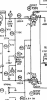
The S-5000 II has -29v after the diodes, then a 4.7k resistor (R90), finally -22v going to a pre-existing 15k double gang output balance pot (R5).

I want to keep the pre-existing output balance pot and add just two more potentiometer, one for each channel, inspired by the IBBA schematic.

So I could do:
1. -29 after diodes
2. 4.7k resistor (R90)
3. 270r resistor (to replace the 15k resistors on the IBBA)
4. 10k bias pot (IBBA)
5. 12k resistor to ground (to replace the 10k resistors on IBBA)

That way I would have a voltage divider where R1 is 4900r (4.7k and 270r in series), and R2 can swing between 12k and 22k (depending if the bias pot is turned one way or the other).

I would obtain a negative voltage, after the IBBA, from -20.50v to -23.65v.

At least that's what I can simulate on that website. Not sure if once wired in the circuit with the tubes the real values would be much different.

Is it a viable option? Would there be any reason why I shouldn't have R90 (4.7k) + 2x 270r resistor (one for channel)?

This is what I mean:

Screen Shot 2020-06-10 at 11.04.03 PM.png

Screen Shot 2020-06-10 at 10.36.38 PM.png

Screen Shot 2020-06-10 at 10.37.37 PM.png
 
Last edited:
I'm not a huge fan of relying on the pot wiper to complete the circuit. Lots of things did that, but if the pot gets crusty you lose bias supply to the tubes. My Pilot amp has new pots because of that.

Did you remove the two 47k resistors from the existing balance pot? That would be enough to mess with things on the IBBA board. You may also need to make that 4.7k resistor smaller, and/or reverse the 15k and 10k fixed resistors to shift the voltage more negative.
 
By pot wiper do you mean the original double gang balance pot pre-existing?

That one was actually a bit crusty already, and in some position one of the gang was malfunctioning. But I replaced it with a NOS part I bought on ebay few weeks ago.
 
yes. Voltage comes into the stock pot via the wiper, the moving part. If that loses contact you get no bias supply to the tubes. Dave's setup is designed so that if the pot fails the tubes get full negative bias supply and just stop conducting rather than melting down.

You can use the existing pot with the IBBA setup, but I'd re-wire it for fail safe operation. Might need to tweak some of the fixed resistor values but thats not a big deal.
 
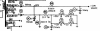
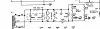
I couldn't manage to find the right values to make the IBBA works, so I decided to copy a bit the schematic of the Sherwood S-5500 III which has bias adjustment pots. To be noted the S-5500 III uses 7868, while my S-5000 II uses 7591.

S-5000 II

Screen Shot 2020-07-06 at 9.53.18 PM.png


S-5500 III

Screen Shot 2020-07-06 at 9.52.45 PM.png \

I replaced the 4.7k resistor (R90) with a 1k resistor. Then added at the -22v source two 10k potentiometer in series with a 20k resistor (I had that in stock rather then 22k). Each bias potentiometer then goes into the double gang balance pot that was already present in my S-5000 II.

Now I'm finally able to set bias for each of the original Sherwood 7591 (made by Westinghouse) tubes to 0.240v each over a 10 ohm cathode resistor.

With a voltage of plate to cathode voltage of 440v (pin 3 to 5), 0.240v should sit at 70% of the max dissipation for 7591.
 
Back
Top Bottom