• The move to the new server is done. There are some software and database maintenance updates in process. This has us passing the hat around to help out. We appreciate any donations. Seriously, even a dollar helps. The payment page may be found here - https://www.audiokarma.org/support.html

IC chip HA12002 "stuck in protect" fix for Sansui AU-D11

PE9ZZ

Event Horizon
Subscriber
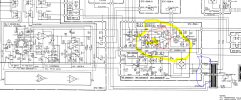
This is actually not exclusively Sansui related nor is the cause stuck in protect. The issue was that at powerup the Sansui AU-D11 amp on my workbench took ages (OK, several minutes) to switch on its output relays even though the amp's outputs were at zero. The cause was the voltage on C4 not rising above 1 V whereas the trigger point is at 3 V. It seems that the HA12002 IC has a design flaw that causes some sort of latchup condition that prevents C4 from charging above that 1 V. The kludge I made was adding an emitter follower between C4 and pin#8, powered from pin#7, the chip's BIAS voltage:

mute_on_kludge.jpg

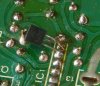
A BC547B or any other suitable universal NPN transistor overrides the latchup like a charm:
botte_bijl.jpg

The HA12002 already was replaced in vain and I could not find any other issue preventing C4 to fully charge.
 
Register to hide this ad
This is actually not exclusively Sansui related nor is the cause stuck in protect. The issue was that at powerup the Sansui AU-D11 amp on my workbench took ages (OK, several minutes) to switch on its output relays even though the amp's outputs were at zero. The cause was the voltage on C4 not rising above 1 V whereas the trigger point is at 3 V. It seems that the HA12002 IC has a design flaw that causes some sort of latchup condition that prevents C4 from charging above that 1 V. The kludge I made was adding an emitter follower between C4 and pin#8, powered from pin#7, the chip's BIAS voltage:

View attachment 2199656

A BC547B or any other suitable universal NPN transistor overrides the latchup like a charm:

View attachment 2199657

The HA12002 already was replaced in vain and I could not find any other issue preventing C4 to fully charge.
I'm not sure yet but I think that HA-12002 on my G-9700 might be causing the protection circuit to fail?
 
Measure the voltage on pin#8.
The schematic says pin #8 should be 4.4v and I'm getting 0.058 and #1 should be 1.1v and it reads 1.8v
The problem is RL 602 doesn't click but the unit powers on as soon as I push the switch there is no red light delay it just turns straight on green.
 
The schematic says pin #8 should be 4.4v and I'm getting 0.058 and #1 should be 1.1v and it reads 1.8v
The problem is RL 602 doesn't click but the unit powers on as soon as I push the switch there is no red light delay it just turns straight on green.
Voltage across D602? Coil resistance RL602?
 
This is actually not exclusively Sansui related nor is the cause stuck in protect. The issue was that at powerup the Sansui AU-D11 amp on my workbench took ages (OK, several minutes) to switch on its output relays even though the amp's outputs were at zero. The cause was the voltage on C4 not rising above 1 V whereas the trigger point is at 3 V. It seems that the HA12002 IC has a design flaw that causes some sort of latchup condition that prevents C4 from charging above that 1 V. The kludge I made was adding an emitter follower between C4 and pin#8, powered from pin#7, the chip's BIAS voltage:

View attachment 2199656

A BC547B or any other suitable universal NPN transistor overrides the latchup like a charm:

View attachment 2199657

The HA12002 already was replaced in vain and I could not find any other issue preventing C4 to fully charge.

I looked at this again and I definately do not "get it".

From the internal schematic of the HA12002 (looking at a Sansui G7500 service manual which has a nice picture of it) it looks for the solution you make sure the pin 8 can not be powered before the pin 7 has some voltage?
I can not deduct a latchup situation from the internal schematic of the IC (of course, the internal schematic may not represent the exact situation).
Is the internal R10 so low the Q12 can pull down the pin 8 voltage so much it can not come up?
As your transistor mod drives pin 8 harder for current, does the latchup consist of the Q12 starts conducting during power up and it does not stop? (unfortunately I do not see any resistance values in the HA12002 schematic, the R10 would be interesting)
 
You can never deduct a latchup situation from an (internal) schematic because it is caused by parasitic components like P-N junctions between doped areas. The substrate is notorious for this which is the reason it must be at the lowest voltage of the IC so all P-N junctions to the substrate are reverse biased. In this case the voltage of pin#7 always leads pin#8 because of the large cap. Still it enters a parasitic mode that I cannot explain but which is fixed with my kludge. I also know from anecdotic experience that these old Hitachi chips are prone to all kinds of issues. This could be due to a manufacturing process flaw that they fixed from a certain date onwards. Which also must be the reason that replacing the IC with a NOS one doesn't fix the issue. In many cases.
 
Makes sense. Only the actual circuit inside an IC is always different from the schematic given. Usually it is called "functional diagram" because it omits the junctions and other structures that are created during the manufacturing of the wafer but do not contribute to the functioning of the IC.
 
This is interesting to know. So the IC diagram is not always as complete as it could be
for the sake of not including un-needed additional confusion.
If I recall correctly the actual number of components can be 3x more than the published schematic. For some (early) chips the actual circuit has been published and those are very hard to follow. Almost all ICs have either functional diagrams or just block diagrams, especially for the more complex functions. MPX decoders seem to be the pivotal point.
 
Hi There,
Came on your post and all the reaction from others. I am struggling with a Denon PMA-790. Where the 500mA rail fuses burn every time I try to switch the amp to ON.
The HA12002 is situated on the print board ETC-558-I. This is also the board where the HA12002 is "living" I have checked and rechecked everything over and over. I must have a blind spot here. Somebody out there who nows??
 

Attachments

  • Denon PMA-790.PNG
    Denon PMA-790.PNG
    278.9 KB · Views: 13
This is not related to the HA12002 even though it lives on that PCB. These fuses blow because the +/-20 V PSU that also resides on that board either is shorted or has a fault itself. There could also be a problem with the +29.6 V rail. The HA is unable to blow any fuse because it has many resistors in its supply lines.

You could use an external PSU to locate the fault causing your fuses to blow. Set the current limit at a low value (say 0.1 A) and then find the spot where that current goes.
 

Attachments

Thanks for you reply.

So f I understand your approach:
1. Amplifier set to OFF
2. Insert current 0,1A via external power supply on the +/-20V rail
3. Analyse where the current goes
 
Back
Top Bottom