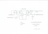
For those who built the Buffer Amplifier to allow for the conversion of the largely unused Reverb jacks into true Preamp Output/Power Amp Input jacks (schematic in post #41), a revised schematic of the Buffer Amplifier is being offered here, superseding the original design. For many who installed this modification, the original design of the buffer is perfectly satisfactory for their needs. Others however, have had the audacity to suggest using the tuner/preamp section of their 400 with a SS power amplifier! In this scenario, the buffer as originally presented offers inadequate LF coupling -- even though the basic buffer circuit itself is more than capable of driving typical SS equipment with ease. In the revised design, this issue has been addressed so that now even when the Preamp Output jacks are used with SS amplifiers whose input impedance is as low as 25KΩ, the buffer will now allow for a full un-attenuated response down to below 20 Hz.
In addition, the buffer's input coupling network has been revised to reduce any loading effects on the balance and volume control circuits of the Fisher, as the volume control is advanced above a 12:00-1:00 setting. Below this setting, the loading presented by the buffer on these circuits is insignificant, but starts becoming significant as the volume control setting rises to 2:00 and above. In this case, the loading presented has no effect on measured frequency response but rather, on the overall gain of the Fisher's control circuits. The revised buffer design offered now presents negligible loading to the balance and volume control circuits, allowing for 99.58% of the Fisher's line stage gain to pass through un-attenuated when the volume control is advanced to full up. As more and more folks turn back to their vinyl collections, total gain of the Fisher becomes important to work with the widest number of cartridges available. Note that when the full bag of modifications was implemented with the original buffer design, the buffer's loading was (in part) accounted for by bypassing the cathode resistors of the line and tone amp stages. When using the new buffer design, bypassing those cathode resistors is no longer necessary, unless additional gain -- beyond that offered by the original design of the 400 -- is desired.
Finally, power for the buffer circuit has been slightly revised as well -- primarily to ease installation when modern IBAM/IBBM modifications are installed. Originally, the buffer was powered off of the old bias circuit feed -- no longer used when fully adjustable modifications were installed. Now, whether such circuits are installed or not, the buffer is supplied from the power supplying the 12AX7 heaters in the phono preamp and line/tone control circuits. Since the line/tone control circuits are typically nearby to where the buffer amplifier is installed, it makes for easy access to the point where power is tapped from. The higher voltage now supplied to the buffer versus that available from the old bias feed circuit also allows the buffer circuit to supply a greater peak un-distorted output as well. The original buffer design had an un-distorted output level capable of driving any typical power amplifier design to full power output, while the new buffer design provides an even greater reserve in peak output capability for that task.
So the revised buffer design offers multiple improvements. But for those who built the original buffer simply to eliminate the Miller occurring at the power amplifier input stage, or use it to drive only external vacuum tube devices, the revised design will offer little if any improved performance over that of the original design. Still, just like Fisher, I'm always looking for ways to improve any modifications I've presented previously, and such is the case then with the buffer amplifier here.
Along with the revised schematic, a pic of the revised buffer installed in a client's early version 400 receiver is presented as well.
Happy listening!
Dave
Installed in an early version 400 receiver. The Speaker Off load resistors originally occupying the location where the buffer amplifier is mounted are now stacked on top of each other, and turned sideways against the T-Strip they connect to:




 Maybe it's time to just order some new parts kits on Amazon.