• The move to the new server is done. There are some software and database maintenance updates in process. This has us passing the hat around to help out. We appreciate any donations. Seriously, even a dollar helps. The payment page may be found here - https://www.audiokarma.org/support.html

Improving the Fisher 400

Problem Solver

Continuing on, the only practical way to really solve the level control roll off problem then is to install a SS buffer circuit between the level control, and the input to the power amps. Since the level control has a loudness circuit associated with it, that makes it a part of the preamp section -- as opposed to being part of the power amp section. Therefore, the buffer circuit should be fed by the level control, with the output of the buffer feeding the new Preamp Out Jack. With the jack straps in place, that means that the consistently low output impedance of the buffer (regardless of level control setting) will then directly drive the input to the internal power amps, and remove the concern for Miller. It also means that when the straps are removed, the Preamp Out Jack represents a nice low impedance source to drive any other power amplifier you might wish -- solid state or otherwise! That lets the 400 operate as a very nice tuner preamp control unit for great versatility in any system.

As for the buffer circuit itself, an op-amp set up to operate as a unity gain amplifier offers the greatest performance return in this application. With good power supply noise rejection, and the capability of very low output impedance, it's a package that's hard to beat. A bifet device was chosen because of its extremely high input impedance, with that figure being in the trillions of ohms. Also, since the chosen device is a dual inline package (DIP), it's very small, and has two op amps built into it, which is perfect for the application. Best of all, being that the device is a TL082/LF353N, you can run right down to the nearest RS and pick one up since it's a store inventory item.

For those concerned about sonics with an op-amp in the signal path, you shouldn't be. Being that the buffer circuit offers no gain (employing 100% NFB), it's about as neutral sounding as any circuit can be, and solves bucket loads of problems, while introducing virtually none. Therefore, it is quite responsible for actually improving sonics, rather than hurting them.

With a basic plan developed then, a small R/S perfboard was used to build the buffer circuitry, and space was made available behind and to the right of the balance control for mounting. This was accomplished by relocating the two 25 ohm 'Speakers Off' load resistors to the other side of the terminal board they connect to, leaving the space between the balance and level controls rather open. The small perfboard could then be mounted in this area with a small L-bracket through one of the cooling holes around the tuner can cap, meaning that once again, no physical alterations were necessary to install the circuit. The location was also ideal, since it allowed for only 3.5 inch shielded leads to connect the signal between the level control, and the input to the buffer amp board. Shielded cable can also cause excessive HF roll off in high impedance circuits if they have any length to them at all, and keeping them short in this case is icing on the cake. With the plan off attack for this problem nearly finished then, all that was left was to figure out how to power it. Remember that neatly folded up white wire that used to supply bias to the output tubes before EFB was installed?

It was perfect. It is relatively well filtered -- well enough for an op amp anyway, and was just lying there, supplying about -18 volts to.......nowhere. Tying the buffer circuit to this source dropped the available voltage down to about -15.5 vdc, which will allow it to develop 5.0 vac RMS at the Preamp Output Jacks if necessary, which isn't necessary for the internal power amps, since they are driven to full power output with just under 2.0 vac RMS at the Power Amp In Jacks. Also, a 5 volt RMS output level will certainly drive almost any external power amplifier to full power output as well if the 400 is used as tuner preamp unit only. Altogether then, the buffer circuit became the perfect answer to the problems imposed by Mr. Miller, and boy oh boy did it solve the problem.

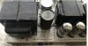
Pics include:

1. The basic buffer circuit board before connecting leads were attached.

2. Mounted and connected up in the space created as discussed.

3. What a difference a buffer makes! Here is the same 10 kHz square wave produced with the level control in the same position as before, driven by the tone stage amplifier, but this time with the buffer installed and operating. It does not change its shape with rotation of the control -- only its amplitude. There simply is no comparison.

4. The schematic of the buffer amplifier, with one channel shown, and the terminals within the DIP representing the other channel.

To be honest, this part of my 400 project was quite challenging -- not only in developing a practical and workable solution that really solved the problem, but also in building and installing it so that the finished job was neat and professional.

The effort was well worth it however, as removing this compromise takes the 400 completely out of the 'receiver' performance category, and moves it to a level where few other pieces of equipment reside. Just as a chain is only as strong as its weakest link, improving all the individual elements in the power amplifier section proper won't solve the problems created by the original level control design. Installing the buffer circuit does however, and then allows the power amplifier modifications to really shine, delivering a realism I have never heard out of a Fisher product before.

Obviously, for those that implement this modification, it does require skill to work with a small circuit board -- or with whatever format you might chose to build the circuit on, and installing it is somewhat tedious, but again, well worth the effort. The basic circuit and idea should be very adaptable to many Fisher products to enhance their performance as well.

In resolving this issue however, one last opportunity to wring out maximum performance from the 400 presented itself -- very much in keeping with the proverbial thread I've been pulling on that I mentioned at the beginning of the EFB thread. By comparison, it is rather simple as compared to the buffer modification, but again, makes the 400 even better, more practical, and much more up to date as well. Next time. But thank heavens, we really are about out of thread!

Dave

EDIT: The Buffer Amplifier circuit has now been revised, which is presented and discussed in post #345 of this thread. The revised design will only offer improved performance in selected scenarios as discussed in the text.

so cool and instructive - asking for a friend, would this also make sense in a Fisher x-100 (early model) ?
 
It will solve the mid level control setting roll-off in virtually any piece of Fisher stereo gear, but if you normally operate the volume control at low positions, then the benefits are less realized because the wipers of the volume controls are so close to ground in that scenario that the output impedance of the control is fairly low, which minimizes the problem of Miller. A "hot" input signal will keep the volume control position low to accomplish this end. What really drove the development of the buffer circuit was when the idea of using the unit as a preamp only came into play, by way of converting the old SpaceXpander jacks into true Preamp Output and Power Amp Input jacks. In that scenario, the buffer was really needed to prevent outside world loads from affecting the output of the Fisher's preamp section when used in that fashion. That it also eliminated any response errors from different settings of the volume control for the internal amplifiers when the straps were in place was an added bonus.

Dave
 
The 2.2 uF cap is a polarized device, because the output terminal of the op-amp (which one lead of this cap connects to) sits at -10 vdc below ground level, while the output side of the cap references ground. Therefore, a non-polarized cap would not be appropriate in this application. The cap can be bypassed with a film cap if desired, but that is typically only necessary in audio applications when the value of the electrolytic cap exceeds 50 uF or so.

Dave
I decided to revise my buffer board to the new circuit to ensure full compatibility to any SS equipment I might want to pair it with. I might be taking you a little too literally, but are you saying not to use a 2.2uf film cap in this location and it must be an electrolytic? I realize a 2.2uf film might be too large to be practical, but I wanted to make sure since I generally prefer to avoid electrolytics when possible.

Also, I wanted to confirm it's fine to remove cathode bypass caps on V10, V11? What about the bypass caps we added to the first section cathodes of V12 and V13? I think removing those will affect the NFB and PI circuits, but wanted to confirm whether to leave those alone?

Thank you, Dave!
 
The buffer output coupling cap doesn't "have" to be an electrolytic, but invariably ends up being one simply due to size. The use of electrolytic caps as an audio coupling mechanism is one of those topics that gets a far worse rap than it should. Again, you might try using a small bypass cap across the electrolytic if you find the its HF characteristics objectionable.

I would strongly recommend leaving the other electrolytic caps you mentioned in place. Removing those associated with V10 and V11 will notably affect the input sensitivity of the amplifier section, while removing those associated with V12 and V13 will affect the distortion and internal output impedance of the power amplifier section. Again, I would suggest that whatever negative impacts that electrolytic caps bring to the table are far outweighed by the benefits they bring, with their negative impacts being easy enough to address when necessary. It would be perfectly fine to add some small film caps across these caps as well if desired.

I hope this helps!

Dave
 
I found and purchased a basket-case Fisher 400 on EBay yesterday for $218. The chassis looks good and it’s got all of its tubes but the description is non-working. If the transformers are good I’ll add the modifications in this thread. The SN is an earlier one; 11550b. I found the schematic for SN 20001 &> but have not found one for the earlier models. Is there a significant difference between a 11550 and 20001 schemo? Thanks!B9013350-FF00-431F-8041-ED1B6D5DC29F.jpeg
 
Not really. But as kappclark noted, the 10001-19999 manual is on the Fisherconsoles.com site. Mine is 15833E, made around late summer '64 and sold Dec. 14, 1964. Yours and mine were probably made within a week of each other. https://audiokarma.org/forums/index.php?threads/400-comes-home-full-circle.759403/
Oh that's going to be a gooood resource for me. Thanks! (that's if the ebay 400 I bought is salvageable). It's missing some/all of the knobs. Chassis looks good. The glass is still there. It looks like it's missing the magic eye bracket. I might have to get crafty. We'll see in a week. It's in the trusty care of the USPS.
 
Last edited:
I am looking forward to reading a great thread to read this weekend ... this Fisher thing is almost like a religion ...

Kapp, thanks for the link. That saved me some time. Now that I've finished a few Magnavox's, I've moved on and finished my first Fisher last week. The forum and the actual work is a lot of fun but listening to the sound quality coming through this receiver is really just mind boggling. It's truly a win/win. Keeps my brain from going to mush, too.
 
Got the updated buffer modifications put in tonight. I also checked the bias' (IBAM) and all the critical EFB voltages and everything is still perfect. I hadn't listened to it in a while, and it still amazes me every time. The sonic improvement these modifications made are very apparent.

IMG_6465.JPG
 
When I connect the record out to My Focusrite Clarett the volume drops on all inputs. Is this a problem that needs to be remedied? I'm also curious about Phono loading specs on the 400 as I would like to get the best possible results out of transferring some vinyl. Hopefully Dave sees this!
 
Street -- The problem is that the input impedance of your Clarett is too low for the Fisher, so it loads down the signal at that point causing the sensitivity of all the inputs to drop.

You can either use an external buffer between your receiver and the Clarett, or, you can install the little SS buffer amplifier I developed to facilitate the Pre Out/Pwr Amp In modification, but use it to buffer the signal being supplied to the Recording Output jacks instead. That way, you wouldn't need the external buffer.

Mating vintage vacuum tube equipment with modern SS equipment can by dicey, as impedance levels -- when the tube device is driving the SS device -- are rarely compatible. The SS buffer would solve that problem completely.

I hope this helps!

Dave
 
Street -- The problem is that the input impedance of your Clarett is too low for the Fisher, so it loads down the signal at that point causing the sensitivity of all the inputs to drop.

You can either use an external buffer between your receiver and the Clarett, or, you can install the little SS buffer amplifier I developed to facilitate the Pre Out/Pwr Amp In modification, but use it to buffer the signal being supplied to the Recording Output jacks instead. That way, you wouldn't need the external buffer.

Mating vintage vacuum tube equipment with modern SS equipment can by dicey, as impedance levels -- when the tube device is driving the SS device -- are rarely compatible. The SS buffer would solve that problem completely.

I hope this helps!

Dave
Thanks for the quick response Dave, Im having trouble picturing how to rewire the buffer on the Schematic to do this. What would a external buffer look like if that is a simpler option? I haven't been under the hood in the 400 in over 5 years when I did all of your modifications so i'm having trouble getting my head back into this.
 
You'd build the buffer circuit as presented, and disconnect the leads currently connected to the Recording Output jacks. The disconnected leads would then be connected to the input of the buffer (where the volume control is shown to connect), and the output of the buffer would connect to the Recording Output jacks.

Dave
 
You'd build the buffer circuit as presented, and disconnect the leads currently connected to the Recording Output jacks. The disconnected leads would then be connected to the input of the buffer (where the volume control is shown to connect), and the output of the buffer would connect to the Recording Output jacks.

Dave

one more thing Dave, does the buffer not being connected between the volume control and preamp output effect anything other than losing the ability to connect a different power amp?

Thanks
Paul
 
one more thing Dave, does the buffer not being connected between the volume control and preamp output effect anything other than losing the ability to connect a different power amp?

Thanks
Paul
From what I remember the buffer circuit was added for two purposes to help aid the space expander jacks become a preamp out/power amp in and next to fix the miller effect from the volume control. if that is the case I don't think I would want to repurpose the buffer.
Does the load from my Clarett have any negative impacts other than volume level? If frequency response is still flat on the recordings im copying then im happy. When im not recording I can leave the record out disconnected. The volume level isn't much of an issue otherwise I run 102+db efficient speakers and have the volume around 9o'clock. anything above 12 o'clock way to loud with my setup even with the record out connected.
 
What performs better spec wise the 400's with the earlier or later transformers?
I think if you search around the forum you would find the answer from a few years ago. From my memory the earlier transformers were a better match unmodified but Dave and others came up with mods to make the later version run just as well. Larry or Dave would be able to answer this much more clearly though.
 
Back
Top Bottom