The last area of great compromise in many Fisher stereo units involves the level control, and the 400 is no exception. In all of the 400, 500, and 800 receivers (as well as many of their integrated amplifiers), the level control is place right at the input to the power amplifier. The upside of this design decision is that low level noise is very well controlled. Indeed, when Fisher receivers are on but turned full down, you'd hardly know they were running save for the dial being lit up. They are simply very quiet creatures. However this design decision, coupled with one other design decision, is what in large part -- in my humble opinion -- creates that rather unique Fisher sound in most of their receiver and integrated amplifiers. I describe it as very smooth and warm, pleasant sound to listen to, but lacking in the fine detail that generates that elusive sense of realism. Turning up the treble slightly doesn't really help, as while that helps to bring out missing detail, it also changes the timbre of the various instruments for no real gain in realism. So what causes this?
Along with the chosen position for the level control, Fisher also chose to almost universally use triode tubes for all of its small signal applications, and the 400 is no different. They are quiet, predictable in performance, and readily available even today. But all triodes suffer from what is known as the Miller Effect. This is a condition whereby high frequency signals at the plate are fed back to the grid by the internal capacitance that exists between these elements within the tube. Of course, it only happens in triodes because there is no intervening screen grid to act as a electrostatic shield to prevent such feedback. To make matters worse, the value of natural capacitance that exists between the plate and grid is effectively multiplied by the Mu (or amplification factor) of the tube. A 12AX7 tube has a Mu of 100. If it has a natural capacitance then of 1 pF or so between its plate and grid, then whatever circuit this tube is used in will perform as if a 100 pF cap is placed directly between the plate and grid of this tube -- independent of any other external components used in a given circuit. Because this capacitance is effectively an internal NFB loop within the tube, if left unchecked, Miller will roll off the high frequency (HF) response of a typical audio amplifier stage quite significantly.
The Miller Effect then is something that either needs to be combated -- if a flat response is required -- or used, if a tapered response is required. Either way, knowing of its presence can allow a circuit to be designed by properly accounting for it.
In the design of the original power amplifier circuit for the 400, Fisher engineers used the capacitance from the Miller Effect that existed within the AF amplifier stage of the phase inverter tube, along with the 47K input grid resistor (and an additional 2 pF plate to grid cap) to produce the very large roll off in HF response required to achieve stability in their design. The problems with their approach were discussed earlier in this thread, but suffice it to say, Miller certainly did the job they wanted it to, and the resulting rolled off square waves showed it. The problem is, Miller is like the Energizer Bunny. Left unchecked, it keeps going, and going, and........
The point of this is that the input of the Fisher 400 power amplifier starts at the input of the 47K grid resistor in the AF amplifier stage (or the 10K input resistor of my revised circuit). When THAT POINT is driven from a low impedance test generator source, then the effect of Miller in the AF amplifier stage is precisely set (in part) by the 47K grid resistor (or the 10K resistor in mine), since the generator itself has very little resistance by comparison. That then produces the 10 kHz square wave forms I provided earlier for both the original design, and my modified design. All this is good, except that in normal use, we don't use a test generator to drive the power amplifier, we use the level control at the output of the tone amplifier stage -- and that's a big problem.
The source impedance provided by the output of the tone amplifier stage to the top of the level control is low enough, but what about all that resistance within the level control itself? At very low settings, the wiper's resistance to ground is very low, therefore keeping the impedance at the input to the power amplifier low. The same thing happens at very high settings as well, where the low output impedance of the tone amplifier keeps Miller in check. But what about the intermediate settings where the level control normally resides? That effectively represents another 250K (!) of resistance added on top of the fixed input grid resistors used in the power amplifier, and allows Miller to have a hay day in the AF amplifier stage. The result is a very, very rolled off response, the amount of which is forever changing with the position of the level control.
Their are ways to deal with this problem, the most notable of which are:
1. Use a preamp that has a consistently low output impedance regardless of how its controls might be set (which can easily be done with an external preamp now if the SpaceXpander jacks are converted to Preamp Out/Power Amp In jacks), and
2. Make the power amplifier input insensitive to any variations in source impedance. Easiest way? Get rid of the triode input stage, and use a pentode input stage. Miller cannot reside in pentodes as previously mentioned. Manufacturers like Scott used this to great advantage in their designs, where the level control -- placed in exactly the same place in the circuit as Fisher does -- has no effect on the pentode AF amplifier section of their (typically) 6U8/7199 inverter/driver tubes.
But changing the Fisher over to using that type of tube changes the inherent nature of the design -- which could be done, but then starts making the Fisher no longer be a Fisher. The goal here is to make the unit be the very best it can be, within what it's original design topology is. If you want a pentode based driver design topology, then go get a Scott.
Changing the preamp section of the 400 to produce an inherently low impedance drive to the power amplifier section regardless of control setting requires more tubes, in a physical design that is already space challenged, so that is not an option either. So what do you do? The roll off is severe, and needs to be corrected if any real gains in realism are to be achieved. I hope I don't lose some of you here (by that I mean turn away), but just like in the power supply section, the answer is SS -- and it is a VERY good answer.
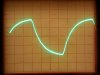
I'll put the details of that answer in my next post, but for now, just to show you how bad the roll of is, a pic is provided of my revised 400 power amplifier with a 10 kHz square wave injected at the top of the level control, with the control turned to a rather typical 10-11 o'clock setting. Eeeeugh! You'd never even know that the source was a square wave!! Want more? With the original design, IT'S EVEN WORSE! With every other aspect of the power amplifier sections now performing so wonderfully, this simply could not stand.......
Dave