• The move to the new server is done. There are some software and database maintenance updates in process. This has us passing the hat around to help out. We appreciate any donations. Seriously, even a dollar helps. The payment page may be found here - https://www.audiokarma.org/support.html

Inductors for dummies - crossover conundrum

davstev

Well-Known Member
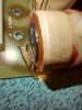
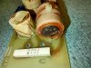
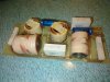
I'm probably in over my head again, that's why I'm turning to AK. I am endeavouring to repair a crossover that I'm sure is faulty, somehow. It's for a Rogers LS7. I'm sure it's faulty because I've tested the woofer and tweeter and they're producing sound when a signal is applied directly. All the internal speaker wiring is good too.

Looking at this crossover... I've pulled the blue e-caps to test with a capacitor tester, they're fine. Film caps should be fine...

But maybe the copper inductors are shot? Not working? How to troubleshoot or test an inductor? I've Got a DMM.

Any suggestions? Thanks for help.
 

Attachments

  • IMG_20230116_220139868.jpg
    IMG_20230116_220139868.jpg
    138.3 KB · Views: 60
  • IMG_20230116_223341009_HDR.jpg
    IMG_20230116_223341009_HDR.jpg
    100.4 KB · Views: 51
  • IMG_20230116_223334760_HDR.jpg
    IMG_20230116_223334760_HDR.jpg
    128.9 KB · Views: 50
Register to hide this ad
Those inductors should be bullet-proof. If your meter can test Henries it should be easy to validate them and their value. If your meter doesn't check Henries, you can check the inductors for an open circuit (although that failure mode is unlikely). Check the resistors on the crossover first though. I've repaired crossovers with bad resistors - most of the time they fail it is not visually apparent in the ceramic resistors.​
 
The first thing to do when troubleshooting a crossover is to get the schematic. Check out https://www.markhennessy.co.uk/rogers/ls7.htm

ls7_crossover.gif


As I understand it, no sound comes from both the tweeter and woofer when a signal is applied to the speaker terminals. The only common point is the speaker terminals and the input section of the PCB. From the input section to the drivers, there is no one single component that could cause both drivers to stop working. If that is your crossover, it looks clean and there are no obvious signs of failure.

The first test is to make sure your amp is working. Swap the speaker to the other channel if you have not done so yet. If the problem follows the speaker, you check the drivers (which you have).

With the crossover installed, I suggest applying a signal to the speaker inputs and then use a signal tracer to see where the signal is lost.I would use a separate tone for testing the woofer and tweeter, say 250 Hz and 4 kHz (above the 3kHz crossover freq).

If you have the equipment, use a real signal generator and an oscilloscope. But a simpler way to test is to apply a tone from a signal generator (phone app works for me) to your amp connected to the speaker. Then use a known working speaker as your signal tester. I use test leads with one end connected to the good speaker and the opposite ends connected to points on the crossover. Trace out the circuit on the schematic and see where you lose your test tone.
 
Check all of the soldering on the back of the circuit board for cold solder joints.
Check that the insulation on the inductor enamel wires was actually scraped off
when the wires were soldered. You can use an ohm meter for this measuring
across the inductors but at the PC trace that they are soldered to.
Check that any slip on connectors are firmly crimped.
 
I'm confused as to what the problem is with the existing speakers. Resistors look fine, coils look fine. Not sure of the caps. What is sound problem?
 
Those inductors should be bullet-proof. If your meter can test Henries it should be easy to validate them and their value. If your meter doesn't check Henries, you can check the inductors for an open circuit (although that failure mode is unlikely). Check the resistors on the crossover first though. I've repaired crossovers with bad resistors - most of the time they fail it is not visually apparent in the ceramic resistors.​
Thanks for this. To test the ceramic resistor, I am just desoldering one end, and testing ohm resistance, correct? I did that for the resistors, and for caps, I tested with a capacitor tester.
I'm confused as to what the problem is with the existing speakers. Resistors look fine, coils look fine. Not sure of the caps. What is sound problem?
The problem is really weak output from both tweeter and woofer. There's also a wooshing sound coming from the tweeter. I connected the speaker wire directly from the amp to the woofer - all good there, good output - then the tweeter, sounding great. So backing up from there, check the wires from xover to speaker. Tested ok for continuity. Then, desoldered one end of all film caps, resistors, and e-caps. All testing ok. Tested continuity from terminals to output of crossover. All seems ok. I am also sure that it's not a problem coming from before the speaker itself (ie. receiver output or speaker wire), tested that. So I am thinking it might be/must be the inductors? I know they rarely fail.
 
You can use an ohm meter for this measuring
across the inductors but at the PC trace that they are soldered to.
Check that any slip on connectors are firmly crimped.

So, just set it to a certain ohm rating on the DMM and then see what reading I get? I am not even sure of the Ohm value of these, but I suppose if it's somehow shot it will read "OL"?
 
use a signal tracer to see where the signal is lost.I would use a separate tone for testing the woofer and tweeter, say 250 Hz and 4 kHz (above the 3kHz crossover freq)."

If you have the equipment, use a real signal generator and an oscilloscope. But a simpler way to test is to apply a tone from a signal generator (phone app works for me) to your amp connected to the speaker. Then use a known working speaker as your signal tester. I use test leads with one end connected to the good speaker and the opposite ends connected to points on the crossover. Trace out the circuit on the schematic and see where you lose your test tone.

Thanks for this, just trying to digest it since I am decent at following instructions but not that experienced in these matters. So: 1) download a signal generator app to my phone 2) run this signal into my amp via cable 3) connect amp to speaker 4) try different tones, one for woofer (250hz) and one for tweeter (4hz) to test. 5) this is where I get foggy. Use DMM? Using one end of DMM test lead, it's connected to terminal directly on working speaker, the other end is touched down to various points on the crosssover, working away from the output point on the x-over and slowly working towards the input terminals? What setting do I have my DMM on? Thanks for humouring a novice here.
 
Last edited:
So, just set it to a certain ohm rating on the DMM and then see what reading I get? I am not even sure of the Ohm value of these, but I suppose if it's somehow shot it will read "OL"?

Set your meter to Rx1, most inductors will be under 1-2 ohms, right open circuit is bad.
 
Back
Top Bottom