• The move to the new server is done. There are some software and database maintenance updates in process. This has us passing the hat around to help out. We appreciate any donations. Seriously, even a dollar helps. The payment page may be found here - https://www.audiokarma.org/support.html

Infinity HTS-10 subwoofer capacitor identification

Lasrever

New Member
I got this subwoofer from a friend for doing some work. It had/has some bad capacitors. I replaced the 3300uf ones that are bad in this pic. But there is one that's totally burnt up and I can't identify it. I'm not schematic savvy sorry to say. Anyone know where I might get this info? There is a little gray flap between the blue wire (spk +) and the black wire (spk -). Just behind the little yellow egg shaped resistor. It is in spot C6. I found a pic that is very blurry but looks like it says 9912 on that cap. So there is a capacitor N9912 but it has leads on each end for crossovers and this is a circuit board layout with both leads out of one end. Anyone have any knowledge if that might be correct cap?
 

Attachments

  • cap pic.jpg
    cap pic.jpg
    102.8 KB · Views: 12
Register to hide this ad
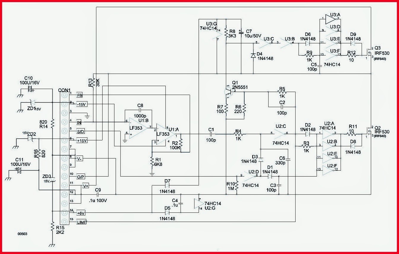
Maybe this is it, not sure, though the module matches. https://masterelectronicsrepair.blogspot.com/2019/03/infinity-bu-80hts-10-powered-sub-woofer.html
That page includes these images. Someone may be able to tell you the component and specs from one of these.
sub-woofer%2Bamp.jpg

amp%2Bmodule.jpg
 
Last edited:
Maybe this is it, not sure, though the module matches. https://masterelectronicsrepair.blogspot.com/2019/03/infinity-bu-80hts-10-powered-sub-woofer.html
That page includes this image. And if it is correct someone may be able to tell you the cap specs.
amp%2Bmodule.jpg

Thank you for your response. I had looked at this before coming here and tried to use the C6 spot identified with 330p. But have no idea what 330p refers to. I just looked more closely using your link, but no where can I find any way to contact the Frank Sharp who generated that blog, sadly.
 
I assume you are trying to identify the values for the cap with the blown top?
What are the values for the cap next to it? They appear similar in size.
I had just Googled picofarads before BS (sorry) posted. They look nothing like the blown cap I'm referring to.
For the most part they look like this..
images
 
Here is a little bit better picture of the gray band left behind after casing dissolved into the void, tucked between the blue and black wire. Don't imagine it's any more helpful but ??? Does 330 picofarads come in many different voltages?
 

Attachments

  • cap pic 2.jpg
    cap pic 2.jpg
    104.8 KB · Views: 9
I assume you are trying to identify the values for the cap with the blown top?
What are the values for the cap next to it? They appear similar in size.
No, I already put 2 new caps in to replace the one that shows as cracked open. The problem is the one that is burned up between the blue and black wires.
 
That does look like a blown electrolytic cap. It also looks like a resistor, or diode?, burned up also.
 
What is silk screened next to that cap. It should read C something. Also the other fried part should have a num error under it. Like D something or R something.
 
So the N9912 is a 330uf cap. There is one that comes in 63v which looks as close as I might get
That does look like a blown electrolytic cap. It also looks like a resistor, or diode?, burned up also.
The most recent photo I got from a guy who is selling a HTS-10 sub online. I asked him to pull the board and send me a photo of that cap. In his pic the cap is shot also :( On the one I have the resistor looks to be in better condition.
 
What is silk screened next to that cap. It should read C something. Also the other fried part should have a num error under it. Like D something or R something.
It say C6 on the circuit board. Based on the N9912 I'm taking a guess it may be a 330uf cap, not to many options. Size wise Maybe a 63 volt that I see available.
 
The picture is showing just one channel? And is it a resistor, or is it black, or gray with a silver or black stripe on it?
 
If it is C6, and not C11, or C11, 63v is fine. Probably better since it blew. And the other bigger caps were on there way out as well. 63v or a little higher might be a good idea for those as well. The 50v caps might have been running on the ragged edge. But that blown capacitor awfully small for a 330uf cap
 
The picture is showing just one channel? And is it a resistor, or is it black, or gray with a silver or black stripe on it?

It is just one channel as it's just for the single subwoofer speaker. There is nothing to look at to tell what it is other than a small black piece of plastic with the two connections to the board. I just measured with my caliper and it does not look like a 330uf cap will fit there. So I'm at a loss atm
 
there is another schematic on the webpage Goodolpg posted that does show the 3300uf caps.
 

Attachments

  • sub-woofer amp.jpg
    sub-woofer amp.jpg
    82.6 KB · Views: 5
Last edited:
If those had been higher Voltage caps they may have lasted longer. That and these plate amps can get pretty hot without much ventilation.
 
before BS (sorry) posted
No apologies as I like the fact the what I post can be stated as what BS said. A load of what I have written fits that description, for sure

The cap you show appears to be a ceramic cap which could easily be a 330pF cap. Not so with electrolytics as they start at maybe 0.22 microfarads. There are other materials for the picoF caps.

I hope we get this amp running. I don't want to dig mine out of the hidden spot it is in and crack it open to see wtf that thing is between the wires. If I do have to dig mine out, let me know where to dive in to get to the item in questions. I don't want to go in the tailpipe to take a look at the battery.
 
Last edited:
Back
Top Bottom