• The move to the new server is done. There are some software and database maintenance updates in process. This has us passing the hat around to help out. We appreciate any donations. Seriously, even a dollar helps. The payment page may be found here - https://www.audiokarma.org/support.html

Infinity Reference Five’s - DIY upgrades?

skyegreen424

brandon
Hey all !!!
I recently picked up some Infinity Reference Five’s. They look amazing, and sound pretty good!
The foams were redone by the previous owner, but I don’t like the way that the mid’s foam was done so I’m gonna redo them myself. I think the foam wasn’t fully glued on and is leaking air.
Anyways, I’m planning to do several modifications to make these sound less boomy. To my ears right now, they do. But I think that’s partially how these were designed.
Anyways, I was hoping that if any of you have had experience working with these speakers or something similar then you could give me advice on whether or not what I’m planning to do would be a good idea? :-D

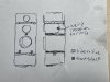
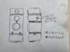
1) I’ve been reading up on what other people have done to vintage cabinets and they generally say that they are underbraced. So, I’m planning to use five 1x1 pine wood braces linking the front and back and both sides. I don’t know how much this will help or if the effects of this are placebos or not - it seems like it wont be and might tighten the bass. The cabinets vibrate a lot when playing music with an emphasis on lower frequencies, and when this happens the lower half of the driver tends to vibrate a good amount. Also, what would be a good glue to use here?
3417F375-9C78-405B-A5BF-121B9B3C2FCC.jpeg

2) I’m planning to use duct seal to dampen the frame of each speaker. Would this be worthwhile in this kind of cabinet design? Previously I’ve done this on a speaker with a passive radiator and that made the speakers sound really nice and tight.

3) Should I also use armacell insulation tape around the edges of the drivers + crossover to seal them in? The foam on these seems pretty flat - I can’t imagine they would provide a good seal

4) Finally, should I mess with the crossovers or leave them be? I have a pretty crappy multimeter but I got some weird readings from a certain resistor on each of the boards. On one board, a 2ohm 5j resistor measures at 1.8 ohms consistently. On the other board, the same resistor measures at 2.6 ohms. I think this resistor is tied to the mid driver. I don’t know if I’m doing the test wrong, but if those measurements seem weird should I replace the resistors? Or, god, should I replace both the caps and the resistors? Would this help me out at all or would this be a waste of time? (I think these are from the early 90s, so about 30 years old now)

If you read thru this whole thing - thank you so much !! ive been lurking here for a bit because I want to make a pretty good sound system comprised of older + less expensive parts. you’ve all been really helpful to give guidance and direction of what the hell to look for hahah. Thank you <3
 

Attachments

  • 000541E4-54A8-44F5-B590-D6EA69F511E3.jpeg
    000541E4-54A8-44F5-B590-D6EA69F511E3.jpeg
    96.4 KB · Views: 11
Register to hide this ad
I would use laminated birch or oak for the braces and not pine. You can also get the rubberized clear seal in spray cans and shoot the interiors of the cabinets. You can also mix some sheep’s wool in with the fill and play with the amounts to change things up. And definitely replace the electrolytic’s out with polypropylene if you can get them to fit. Or at minimum go with new electrolytic’s - you can also go in parallel 75% electrolytic and 25% poly adding up to the original values. I use epoxy on the braces. And you want both left and right to match so the resistors will need to be replaced. The inductors and any existing polys should be fine. If there are pots, open them up and clean/test thoroughly.

It’s very likely that any electrolytic’s over 20+ years old will be out of spec. You will hear the difference when you are done for sure.
 
You can also glue square stock into the corners to stiffen things up, just don’t go to big and radically change the interior displacement.
 
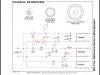
Hifiengine has the tech sheet. The emit needs a poly and the in signal 75 uf could be replaced with a 50 electrolytic + 25 poly, while the caps that go between minus and positive could be electrolytic’s.
upload_2021-7-1_22-50-10.jpeg
 
Definitely do items 1 and 2. Also check to make sure the midrange chamber is completely sealed. I have a pair of the Reference Fours and one of the midrange chambers was loose and caused all kinds issues between the midrange and the woofer.
 
You can also glue square stock into the corners to stiffen things up, just don’t go to big and radically change the interior displacement.
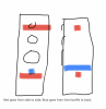
Would this just be a square piece of wood glued into each corner? Also, when you say don't radically change the interior displacement, would the drawing I did be too much? I actually want to change things a little bit because I ended up getting a 1x2 maple wood - this is what I'm thinking nowScreen Shot 2021-07-02 at 1.06.55 PM.png

Hifiengine has the tech sheet. The emit needs a poly and the in signal 75 uf could be replaced with a 50 electrolytic + 25 poly, while the caps that go between minus and positive could be electrolytic’s.
View attachment 2274240
What benefit would this provide rather than using a 75uf electrolytic only or poly only? I don't really know how this stuff works hahah - would this be a cost benefit or sound benefit?
 
Definitely do items 1 and 2. Also check to make sure the midrange chamber is completely sealed. I have a pair of the Reference Fours and one of the midrange chambers was loose and caused all kinds issues between the midrange and the woofer.
Is there any way to verify the seal besides the feeling of the chamber? It feels pretty damn stuck in there - maybe I should reline it just in case? I haven't checked where the wires leave from either - maybe there's an air gap there? I could probably just hot glue them in if so
 
Is there any way to verify the seal besides the feeling of the chamber?

With all the drivers installed and secured, gently push down on the woofer. If you see the midrange move in response to the woofer being pushed, you have air leaking between the two chambers. If the midrange is completely still when you press on the woofer then the chambers have a good seal between them.
 
With all the drivers installed and secured, gently push down on the woofer. If you see the midrange move in response to the woofer being pushed, you have air leaking between the two chambers. If the midrange is completely still when you press on the woofer then the chambers have a good seal between them.
Okay then they're definitely sealed B-) I remember testing that because one of the mid drivers was acting weirdly - it turned out the foam on the mid wasn't properly attached. but there is a seal between the rest of the cabinet and the midrange driver
 
Would this just be a square piece of wood glued into each corner? Also, when you say don't radically change the interior displacement, would the drawing I did be too much? I actually want to change things a little bit because I ended up getting a 1x2 maple wood - this is what I'm thinking nowView attachment 2274441


What benefit would this provide rather than using a 75uf electrolytic only or poly only? I don't really know how this stuff works hahah - would this be a cost benefit or sound benefit?
It’s cost. For in signal polypropylene is important and even low uf can run $$.
Would this just be a square piece of wood glued into each corner? Also, when you say don't radically change the interior displacement, would the drawing I did be too much? I actually want to change things a little bit because I ended up getting a 1x2 maple wood - this is what I'm thinking nowView attachment 2274441


What benefit would this provide rather than using a 75uf electrolytic only or poly only? I don't really know how this stuff works hahah - would this be a cost benefit or sound benefit?
The polypropylene 75 uf run $25.00 while the electrolytic’s are $2.50. Polypropylene in signal are critical to proper sound while the caps that connect from + to - are less critical. Always go with the best quality poly on your tweeters. Ideally on the mids as well. But you can take an electrolytic and add a poly in parallel where the two values total the required uf. In your case that’s 75uf, so a 68 uf electrolytic plus a 6.8 uf poly = close enough to 75uf.
 
Would this just be a square piece of wood glued into each corner? Also, when you say don't radically change the interior displacement, would the drawing I did be too much? I actually want to change things a little bit because I ended up getting a 1x2 maple wood - this is what I'm thinking nowView attachment 2274441


What benefit would this provide rather than using a 75uf electrolytic only or poly only? I don't really know how this stuff works hahah - would this be a cost benefit or sound benefit?
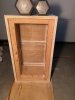
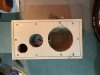
This image shows how the square pieces fit. The ones behind the front baffle are 1 inch while the rest are 1/4. The front baffle is then bolted to the 1 inch framing. The woofers were designed to work with a specific displacement. When you add up the cubic inches the braces add up to you would be surprised. This cabinet needed to be deepened by a full 1 1/2 inches to offset these braces. I have also seen solid wood panels added to the exterior to reduce harmonicsupload_2021-7-2_13-45-33.jpeg
The bolts
upload_2021-7-2_13-47-31.jpeg
 
This image shows how the square pieces fit. The ones behind the front baffle are 1 inch while the rest are 1/4. The front baffle is then bolted to the 1 inch framing. The woofers were designed to work with a specific displacement. When you add up the cubic inches the braces add up to you would be surprised. This cabinet needed to be deepened by a full 1 1/2 inches to offset these braces. I have also seen solid wood panels added to the exterior to reduce harmonicsView attachment 2274655
The bolts
View attachment 2274659
Is that a custom build? Seems interesting - so you're saying that the best option would be to brace the sides of the cabinet rather than go through the space of the cabinet? I don't really want to modify the exterior of the cabinet nor remove the baffle, so would I be able to get away with the cross beams I was thinking?
 
Yes, it was a complete upgrade of the original RSb design. https://audiokarma.org/forums/index.php?threads/infinity-rsb-reincarnated.904243/

I can’t find the pictures I saved, but I will try and describe the exterior panels. The panels were 1/2 inch solid wood and added to the right and left sides of the cabinets. The front and top edges were beveled and the top edge was cut at an angle from below the tweeter in the front to the top at the back. They looked outstanding and gave the speakers a two tone very high end look. He just roughed up the cabinets where the panels fit and glued fastening with counter sink screws - filling the holes with matching plugs. Boom no more unwanted harmonics.
 
Hifiengine has the tech sheet. The emit needs a poly and the in signal 75 uf could be replaced with a 50 electrolytic + 25 poly, while the caps that go between minus and positive could be electrolytic’s.
View attachment 2274240

Alright - I opened up the cabinet again to take a look at the capacitors. Here is what I found online based on what you recommended.

Infinity schematic crossover


75 UF in signal replacement - https://www.parts-express.com/Dayton-Audio-PMPC-6.8-6.8uF-250V-Precision-Audio-Capacitor-027-238 + https://www.mouser.com/ProductDetail/Vishay-BC-Components/MAL202135689E3?qs=IODwLvXzwT1DMUkyeIcIUw== 5.59 + 1.72 = 7.31 * 2 = 14.62


175.0 UF out of signal replacement - https://www.mouser.com/ProductDetail/Nichicon/UKL1A151KPDANA?qs=osObagmpUM2Y%2BH1hyYGA8g== + https://www.mouser.com/ProductDetail/United-Chemi-Con/EGXF251ELL240MJ20S?qs=8BXZADTIn4F6lltHBzyyug== 0.48 + 1.44 = 1.92 * 2 = 3.84


6.0 UF in signal replacement - https://www.parts-express.com/Dayton-Audio-PMPC-3.0-3.0uF-250V-Precision-Audio-Capacitor-027-220 x2 (I don’t see this capacitor visible anywhere on my crossover) 7.18 * 2 = 14.36


75 UF out of signal replacement - https://www.mouser.com/ProductDetail/Vishay/TE1308-E3?qs=F0bBuU9YDEyP3NsKn/3x0g== (I only see one 75UF capacitor) 5.26 * 2 = 10.52


2ohm5j resistor replacement - https://www.parts-express.com/Mills-2.5-Ohm-12W-Non-Inductive-Resistor-005-2.5 6.98 * 2 = 13.96 (can I use something cheaper?)


0.5ohm resistor replacement - https://www.parts-express.com/Mills-0.5-Ohm-12W-Non-Inductive-Resistor-005-.5 or https://www.parts-express.com/0.51-Ohm-5W-Resistor-Wire-Wound-5-Tolerance-015-.51 (latter is cheaper) 6.98 * 2 = 13.96 or 0.86 * 2 = 1.72


Differences in what I observed on the physical crossover


Mystery capacitors: blue M9126 (glued in), 3.6 UF capacitor 100VDC


3.6 UF unknown capacitor - https://www.parts-express.com/Dayton-Audio-PMPC-3.0-3.0uF-250V-Precision-Audio-Capacitor-027-220 + https://www.mouser.com/ProductDetail/Nichicon/UKL2AR68KDD1TA?qs=WzFAwlZZqiG6ttpp2Fkh8A== 3.59 + 0.41 = 4 * 2 = 8

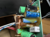
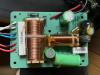
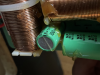
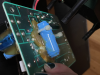
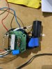
Now, I might have mistaken what is a capacitor and what isn't. There are these vaguely capacitor looking things that look like coils wrapped in blue plastic. Also, how do I tell if a capacitor on Mouser is polarized? Also, is having this many coupled capacitors going to be an issue in regards to heat/space? Do they need to be attached to the board or can I wire them? Also, I've attached pictures of one of my crossovers.

tempImagevTWMqI.png tempImageruNrMo.png tempImageioOIPS.png tempImageEyR8SN.png
 
The blue wrapped ferrite rods are inductors. Don’t mess with those, they are not capacitors. Mouser does have bipolars and the data sheets will tell you if they are or not. Chances are they won’t be. All the caps from parts express in the crossover section will be bipolar. To be safe get all your parts from parts-express. Take your time and examine all the parts currently installed, the greens all appear to be electrolytics. Just make sure you match the uf values. You can go higher on voltages - don’t go lower. The polys are here and the Dayton’s will be fine quality https://www.parts-express.com/speak.../metalized-polypropylene-crossover-capacitors
The electrolytics are here https://www.parts-express.com/speak...acitors/non-polarized-electrolytic-capacitors. Crossover caps must be non-polarized ie bipolar. As for the resistors, the non inductive Dayton’s are good quality. The mills are excellent, but the Dayton’s are fine. Just make sure you match the ohms and voltages. You don’t need a higher voltage than what’s currently installed. The tech sheets don’t always match what’s installed. Just use the values of what’s actually there. Also Google how to replace a radial with an axial capacitor as you probably won’t find proper radials. Capacitors in parallel add 1 to 1 for capacitance but not voltage so if you add two together both voltages need to be at or higher than what is already there.
 
This is how I installed axial polys to fit in place of the radials. And these rs5000’s sound and perform amazing. You can also put them on their ends and bend one of the leads but don’t bend it close to where the lead enters the cap. Search for rs5000 on audiokarma.
 
My phone for some reason won’t post pictures to ak. Yes you can use short high quality jumpers. Just make sure the big polys are supported and not just hanging on the wires
 
The blue wrapped ferrite rods are inductors. Don’t mess with those, they are not capacitors. Mouser does have bipolars and the data sheets will tell you if they are or not. Chances are they won’t be. All the caps from parts express in the crossover section will be bipolar. To be safe get all your parts from parts-express. Take your time and examine all the parts currently installed, the greens all appear to be electrolytics. Just make sure you match the uf values. You can go higher on voltages - don’t go lower. The polys are here and the Dayton’s will be fine quality https://www.parts-express.com/speak.../metalized-polypropylene-crossover-capacitors
The electrolytics are here https://www.parts-express.com/speak...acitors/non-polarized-electrolytic-capacitors. Crossover caps must be non-polarized ie bipolar. As for the resistors, the non inductive Dayton’s are good quality. The mills are excellent, but the Dayton’s are fine. Just make sure you match the ohms and voltages. You don’t need a higher voltage than what’s currently installed. The tech sheets don’t always match what’s installed. Just use the values of what’s actually there. Also Google how to replace a radial with an axial capacitor as you probably won’t find proper radials. Capacitors in parallel add 1 to 1 for capacitance but not voltage so if you add two together both voltages need to be at or higher than what is already there.

Alright - I've got my final list! I'm happy I didn't order anything yet hahah - I didn't know that about capacitor voltages. Thank you for the heads up !!

For future reference here's what I am planning to order -
Final list of components per crossover :

75 UF 100V in signal - 1x Dayton Audio PMPC-6.8 6.8uF 250V Precision Audio Capacitor + 1x 68uF 100V Electrolytic Non-Polarized Crossover Capacitor


175 UF 100V out of signal - 1x 150uF 100V Electrolytic Non-Polarized Crossover Capacitor + 1x 15uF 100V Electrolytic Non-Polarized Crossover Capacitor + 1x 10uF 100V Electrolytic Non-Polarized Crossover Capacitor = 175UF


6.0 UF 100V in signal - 2x Dayton Audio PMPC-3.0 3.0uF 250V Precision Audio Capacitor


3.6 UF 100V unknown - 1x Dayton Audio PMPC-3.0 3.0uF 250V Precision Audio Capacitor + 1x Dayton Audio DMPC-0.68 0.68uF 250V Polypropylene Capacitor = 3.68 UF (im assuming this is fine cus the original cap is 10% tolerance)


2ohm5j resistor - 1x Mills 2.5 Ohm 12W Non-Inductive Resistor


0.5ohm resistor - 1x 0.51 Ohm 5W Resistor Wire Wound 5% Tolerance
 
Back
Top Bottom