• The move to the new server is done. There are some software and database maintenance updates in process. This has us passing the hat around to help out. We appreciate any donations. Seriously, even a dollar helps. The payment page may be found here - https://www.audiokarma.org/support.html

Installed a wifi board (Arylic) - now Tick, tick, tick sound, grrrrrrr!

Toiler

Member
Hello all! I am Rob, up in Edmonton Canada. I am NOT a competent electronics technician, only a very basic knowledge guy who likes looking at videos on YouTube and likes vintage gear. I have a Pioneer SX-850 receiver that was fully serviced by a qualified tech a couple months back And working in proper order.
This past weekend I chose to install an Arylic Up2Stream Mini, to provide streaming from my smartphone via wifi. I had success (generally speaking). But there is a PROBLEM!

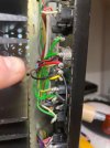
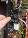
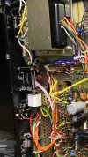
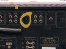
First, here’s what I did to install. I needed 5 volt, 1 amps to power the Arylic unit, so I used a little white, square Apple branded USB charger That I had sitting around. I connected one blade of that little cube shaped USB charger to the Pioneer SX-850 ground (with simple wire and solder) on the other blade to the switched line power (with a 1 amp glass fuse in between). I then plugged a USB cable from the charger to the Arylic Up2Stream mini. I connected (soldered directly) each of the so R and L, + and - speaker connections from the Arylic, to the Pioneer unit’s circular looking, rec/play input (the one that really now one EVER uses. inside the Pioneer unit, these rec/play connections are actually jumpEd across to the Tape 2 inputs with soldered wire connections that were done during the Pioneer’s original manufacturing.

Of not (possibly): I also replaced the original non-polarized cord with a new polarized cord. The original cord was 18 gauge and I replaced it with a 16 gauge cord. I believe I did ensure that this work was done correctly, ie line and common are connected into the Pioneer in the proper manner.

HERE’S THE PROBLEM: When I turn on power, I hear a fast but fairly quiet, ’clicking‘ or ‘ticking’ coming noise through the speakers (not a mechanical clicking like the relay switch or anything like that). Within about 10 or 15 seconds thereafter, that fast clicking reduces to a slower clicking. The change in the pace of the clicking (I am pretty certain), coincides perfectly with the initial ‘searching’ by the Arylic unit for a connection to wifi. As I mentioned, once connected to wifi, pace of the clicking slows dramatically. Of note, the clicking sound comes through the speakers NO MATTER WHAT INPUT I SELECT!
This situation is exceedingly annoying and very disappointing.

Direction on how to correct this issue would be greatly appreciated!

Here is a link to the Arylic Up2Stream Mini https://www.boomaudio.de/media/pdf/90/60/e6/Up2Stream_Mini_V3-0_200408.pdf
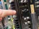
 

Attachments

  • IMG_6770.jpeg
    IMG_6770.jpeg
    115.9 KB · Views: 45
  • IMG_6771.jpeg
    IMG_6771.jpeg
    91 KB · Views: 44
  • 72431264500__991B5FF3-2D6A-4EA9-AC44-C62B343669B1.jpeg
    72431264500__991B5FF3-2D6A-4EA9-AC44-C62B343669B1.jpeg
    124 KB · Views: 44
  • View recent photos.jpeg
    View recent photos.jpeg
    124.9 KB · Views: 44
  • IMG_2066.jpeg
    IMG_2066.jpeg
    81.8 KB · Views: 45
Register to hide this ad
Unshielded digital circuits combined with unshielded vintage analog circuits are not a good combination. I'd first try to build a grounded metal box around the Up2stream. You can experiment first with some aluminium foil (make sure you insulate the circuitry first - you only want the foil touching the Pioneer's chassis. You might also need a choke around any cables exiting the module.
 
I connected one blade of that little cube shaped USB charger to the Pioneer SX-850 ground (with simple wire and solder) on the other blade to the switched line power (with a 1 amp glass fuse in between).
How are you powering this usb charger? I' d just plug it to the wall , not to the pioneer amp. The same with your digital device. Install everything outside the amplifier, check everything works ok. And then move it closer to the amplifier until you start to hear the interferences.
 
How are you powering this usb charger? I' d just plug it to the wall , not to the pioneer amp. The same with your digital device. Install everything outside the amplifier, check everything works ok. And then move it closer to the amplifier until you start to hear the interferences.
Thanks. You do understand that I’ve described how i’ve ALREADY installed everything? I included photos as well.
 
Unshielded digital circuits combined with unshielded vintage analog circuits are not a good combination. I'd first try to build a grounded metal box around the Up2stream. You can experiment first with some aluminium foil (make sure you insulate the circuitry first - you only want the foil touching the Pioneer's chassis. You might also need a choke around any cables exiting the module.
I’ll work on some type of shielding. Will post if/when I discover an effective solution. Thanks for your thoughts.
 
Thanks. You do understand that I’ve described how i’ve ALREADY installed everything? I included photos as well.
I don't get how did you "solder" the USB charger, which (I guess) is supposed to be connected to the mains, not the amplifier chassis. I want to understand if you are doing some dangerous connection. You mentioned you soldered it to "ground", which usually means the amplifier chassis. The chassis shouldn't be connected to the mains by any mean.
 
I don't get how did you "solder" the USB charger, which (I guess) is supposed to be connected to the mains, not the amplifier chassis. I want to understand if you are doing some dangerous connection. You mentioned you soldered it to "ground", which usually means the amplifier chassis. The chassis shouldn't be connected to the mains by any mean.
The chassis should be connected to mains earth unless it is double insulated. I'm not sure if the Pioneer is double insulated or not. One picture I found online shows it with an IEC mains inlet which would suggest it isn't double insulated and should be connected to mains earth. Another picture I found shows the amplifier with a captive mains cable and the shape of the cable suggests it's only two-conductor, which leads me to think it is double insulated and shouldn't be connected to mains earth. :dunno:Maybe the one with an IEC mains inlet has been modified.
Either way, yes, safety should be a primary concern.
Whether the chassis is connected to mains earth or not, it's generally not good practice to use the chassis as a conductor for 0V connections.
The board shown in the third picture appears to have a solder pad marked GND near to a group of four other solder pads, one of which is marked GND and one of which is marked AGND. I can't be absolutely sure of that because it's difficult to see. Anyway, audio ground and digital ground seem to be two separate things in digital circuits. I suspect the way that board is connected to the Pioneer's 0V system is where the problem will be found.
 
FWIW, And you`re using a Apple brand SMPS "charger" wall wart as the power source.
Not intending to make a dig at Apple products, but often, I suspect, most cube type USB chargers, are not only often SMPS based, they usually have little to no electrical input/output noise filtering designed into them, as their ORIGINAL intended purpose is to "charge" USB device`s internal batteries, and not to power any, sensitive to noise stand alone audio based devices, so their is not much, or any, reason to incorporate good EMI filtering or even internal shielding of the wall wart`s noisy as hell switching and battery charging regulating circuitry.

And installing the USB charger inside the receivers chassis, will certainly be asking for the plastic encased charger`s radiated noise to be readily injected into the receiver`s sensitive circuitry, in this effort for a "Clean" installation !

Not a good idea, IMO/E without some careful thought about input/output filtering and shielding !

Good luck straightening this out to your satisfaction.
 
The chassis should be connected to mains earth unless it is double insulated. I'm not sure if the Pioneer is double insulated or not. One picture I found online shows it with an IEC mains inlet which would suggest it isn't double insulated and should be connected to mains earth. Another picture I found shows the amplifier with a captive mains cable and the shape of the cable suggests it's only two-conductor, which leads me to think it is double insulated and shouldn't be connected to mains earth. :dunno:Maybe the one with an IEC mains inlet has been modified.
Either way, yes, safety should be a primary concern.
Whether the chassis is connected to mains earth or not, it's generally not good practice to use the chassis as a conductor for 0V connections.
The board shown in the third picture appears to have a solder pad marked GND near to a group of four other solder pads, one of which is marked GND and one of which is marked AGND. I can't be absolutely sure of that because it's difficult to see. Anyway, audio ground and digital ground seem to be two separate things in digital circuits. I suspect the way that board is connected to the Pioneer's 0V system is where the problem will be found.
I actually mean the chassis shouldn't be connected to mains neutral or live. I understood the chassis being used as neutral in this application. But I'm not seeing the whole picture. As mentioned, safety should be the 1st thing to address.
 
I actually mean the chassis shouldn't be connected to mains neutral or live. I understood the chassis being used as neutral in this application. But I'm not seeing the whole picture. As mentioned, safety should be the 1st thing to address.
The chassis is typically connected to DC power supply ground. In the US, you can cannot 100% guarantee correct polarization from any power cord, so this would be a huge safety hazard. However, it didn't prevent manufacturers of older tube equipment from connecting the chassis to one side of the power cord. Luckily this was outlawed decades ago.
 
streaming from my smartphone via wifi.
I use an old Pioneer SX-636 for my desktop amp. If my cellphone is within 2 feet of my amp, I get morse code like noises coming thru the speakers, because the old amp is picking up the signal from the phone. I'm not using the phone to stream or anything, it's just sitting there.

jeff
 
I use an old Pioneer SX-636 for my desktop amp. If my cellphone is within 2 feet of my amp, I get morse code like noises coming thru the speakers, because the old amp is picking up the signal from the phone. I'm not using the phone to stream or anything, it's just sitting there.

jeff
Yes it`s just sitting there radiating/spewing quite a bit of RFI/EMI noise while it`s just simply powered up, or actively engaged doing something !
 
I don't get how did you "solder" the USB charger, which (I guess) is supposed to be connected to the mains, not the amplifier chassis. I want to understand if you are doing some dangerous connection. You mentioned you soldered it to "ground", which usually means the amplifier chassis. The chassis shouldn't be connected to the mains by any mean.
Hi Bill. Thanks for your reply. To answer your query… in my own words (I’m not an electrician or a tech), there are two wires in the electrical cord which bring mains powers from the wall outlet into the Pioneer receiver. I essentially soldered each of these two wires to each of the two blades of the USB power converter. So, line in (power) from the mains go into the receiver, then through it’s ‘on/off’ switch - that is where I connectEd one of the blades. The other plug in blade from the USB is connected to a ‘common’ wire. I should note that the ‘common’ wire I connected to does eventually GO TO THE CHASSIS/metal frame.
 
I think we are mixing concepts and definitions here, adding that I live in a different country with different voltages and a different language. Please correct me if I'm wrong, but I understand that the 2 wires carrying main AC VOLTAGES (120V AC or 220V AC down here), should be connected only to the transformer primary winding (fuse and power switch included in this circuit) and nothing else. The rest of the amplifier (chassis included) should be isolated from that main AC Voltage with the transformer.
 
If it's not solved by the ground discussion, it does seem to be an unavoidable RF tradeoff. Shielding the card sufficiently so it can't inject noise into the audio circuits will likely shield its Wifi connection too. This has a switched AC socket on the outside right? I've used those with Bluetooth cards and apple usb blocks. All external. It turns on with the receiver and is invisible behind it. As good as internal -- but with no interference.
 
The chassis should be connected to mains earth unless it is double insulated. I'm not sure if the Pioneer is double insulated or not. One picture I found online shows it with an IEC mains inlet which would suggest it isn't double insulated and should be connected to mains earth. Another picture I found shows the amplifier with a captive mains cable and the shape of the cable suggests it's only two-conductor, which leads me to think it is double insulated and shouldn't be connected to mains earth. :dunno:Maybe the one with an IEC mains inlet has been modified.
Either way, yes, safety should be a primary concern.
Whether the chassis is connected to mains earth or not, it's generally not good practice to use the chassis as a conductor for 0V connections.
The board shown in the third picture appears to have a solder pad marked GND near to a group of four other solder pads, one of which is marked GND and one of which is marked AGND. I can't be absolutely sure of that because it's difficult to see. Anyway, audio ground and digital ground seem to be two separate things in digital circuits. I suspect the way that board is connected to the Pioneer's 0V system is where the problem will be found.
Ohhhhhhh! I like your observations regarding GND and AGND. When I contacted Arylic and asked if I should conn3ct BOTH GND and AGND, when connecting Left and Right audio, the up’s said YES. I simply connected them both to the negative side of the tape 2 input. Perhaps I should pull the GND off and see if that makes a difference?
 
If it's not solved by the ground discussion, it does seem to be an unavoidable RF tradeoff. Shielding the card sufficiently so it can't inject noise into the audio circuits will likely shield its Wifi connection too. This has a switched AC socket on the outside right? I've used those with Bluetooth cards and apple usb blocks. All external. It turns on with the receiver and is invisible behind it. As good as internal -- but with no interference.
That may be an option to go with. I was hoping to tuck everything inside and out of the way... I agree that shielding (like a Faraday cage), will likely interfere with wifi (although there is a short antenna that could poke through) but the Bluetooth antenna is on the board itself so that will likely be mom-functional.
 
Back
Top Bottom