

You are using an out of date browser. It may not display this or other websites correctly.
You should upgrade or use an alternative browser.
You should upgrade or use an alternative browser.
Installing a new 2772 into an X1

C1, C2 (0.047µF) & C3 (0.27µF) are the 3 film capacitors, and R601 (33Ω) & R602 (5.6Ω) are the only 2 resistors on the board. (NB: these parts are not present on a Mk1 board).
See post #1 for the parts list for the new (replacement) board or the Mk2 (OEM) board.
See post #1 for the parts list for the new (replacement) board or the Mk2 (OEM) board.
Last edited:

slimecity
Super Member
Thanks Hyperion - saw the parts list but wanted to confirm the component ID's vs the PCB screening.C1, C2 (0.047µF) & C3 (0.27µF) are the 3 film capacitors, and R601 (33Ω) & R602 (5.6Ω) are the only 2 resistors on the board. (NB: these parts are not present on a Mk1 board).
This PCB is starting to look pretty good stuffed, next up I need to tackle cannibalising the old board.
I have a V1 board too, so have some issues with that one 6-pin connector.....
Good stuff.

Bigdrive
Active Member
Thanks @Ronito6 for the great board! the quality is great. Concerning the connectors, I had originally ordered wm11696-nd before I got the board. While they could be made to work, its not close enough for me. I am now looking at a31678-nd with a a122432-nd. the pitch looks perfect and its gold pin both sides. Can anyone see a problem using these?
https://www.digikey.ca/product-detail/en/3-641208-4/A31678-ND/769821
https://www.digikey.ca/product-detail/en/3-641151-4/A122432-ND/1862272
Cheers,
Gord
https://www.digikey.ca/product-detail/en/3-641208-4/A31678-ND/769821
https://www.digikey.ca/product-detail/en/3-641151-4/A122432-ND/1862272
Cheers,
Gord
The pitch on the 6-way (wire-to-board) connector (as used on the Mk2 board) is 5mm, but there is a 7.5mm spaced pin at the end. the 2 x 3-way (wire-to-board) connectors pitch is also 5mm, with a pin spaced at 7.5mm.
The connectors linked in your post above have 4mm pin spacing (3.96mm) - but you shouldn't need any of these as this is the pin spacing for the plug in MM & MC boards, which will be on a Mk1 or a Mk2 board by default - so.... I am not sure what you will be using the above connectors for? - unless... maybe you are making a board up from scratch to replace a missing one?
The connectors linked in your post above have 4mm pin spacing (3.96mm) - but you shouldn't need any of these as this is the pin spacing for the plug in MM & MC boards, which will be on a Mk1 or a Mk2 board by default - so.... I am not sure what you will be using the above connectors for? - unless... maybe you are making a board up from scratch to replace a missing one?
Bigdrive
Active Member
When I checked the pitch of the 2x3 on the new board it looks like it would accept a .396 pitch with the end pin only being out .5mm. My original board is version 1 so I will have to address the second 6 pin connector to convert it to the two 3 pin connectors. I would be using the shown header and connector to make that conversion as shown on post #1 "Issues when installing from version one board. Not the connection for the MM/MC boards.
slimecity
Super Member
I have the same issue as you Bigdrive - let me know what you come up with.When I checked the pitch of the 2x3 on the new board it looks like it would accept a .396 pitch with the end pin only being out .5mm. My original board is version 1 so I will have to address the second 6 pin connector to convert it to the two 3 pin connectors. I would be using the shown header and connector to make that conversion as shown on post #1 "Issues when installing from version one board. Not the connection for the MM/MC boards.
I ordered some individual PCB pins from RS but they are way too small.
I will be leaving my phono motherboard in there once its done - so Im considering just hard-wiring those 6 points in there by solder the wires in direct.

Ronito6
Super Member
Hi guys - can you please advise which caps are C1, C2 and C3 in this PCB?
Which resistors are R602 & R602?
thanks
PARTS LIST
Needed to complete the board.
6 x Omron G5V-2-DC24 signal relays.
1 x 33Ω ¼ watt resistor.
1 x 5.6Ω ¼ watt resistor.
3 x 1N4003 rectifier diode. (Replacing 10D1)
4 x 470µF 35V electrolytic capacitors. (I used 63V here)
2 x 0.047µF 100V film capacitors.
1 x 0.27µF 100V film capacitor.
But to answer your question:
C1 and C2 are 2 x 0.047µF 100V film capacitors.
C3 is 1 x 0.27µF 100V film capacitor.
Thanks for asking. It helps to clear up the process for others.
Bigdrive
Active Member
I will be leaving my phono motherboard in there once its done - so Im considering just hard-wiring those 6 points in there by solder the wires in direct.
I agree with you. Very little requirement for the F-2772 to come out in the furture but its the regulated power supply board and its leads that may have to come out. If there is no disconnect then my thought is I would have to remove the F-2772 to check/shift for access the power supply. I have rechecked the pitch on the board to ensure the forth pin will go in the hole without any mods and it will. The 3.96 pitch to me should work, enough so that I will order it today.
The ones I have now are these with the other connector that goes with it.
https://www.digikey.ca/products/en?keywords=wm11696-nd
There pitch is .300 and could be forced to work, but I am not going there. I also noticed on my pick for the plug it will only take 24awg so that will be changed to the largest in that series at 18awg and the drawing gives the detail of largest insulated wire width of .094. I checked the wire and its .072 so it will work.
The pitch on the 6-way (wire-to-board) connector (as used on the Mk2 board) is 5mm, but there is a 7.5mm spaced pin at the end. the 2 x 3-way (wire-to-board) connectors pitch is also 5mm, with a pin spaced at 7.5mm.
I could not find 5mm connectors. I did find these that I think are very close and might work if you wanted to keep the disconnect available. Doing the math, OC original 3 pin is 12.5mm from first to last pin. In the 3.96 (4mm) 4 pin the OC first to last pin is 12mm. Break off the third pin and fill connector with epoxy so it is keyed.
Cheers,
Bigdrive
Active Member
This is the 18awg one. Orange is the only color! It should look great with the purple board.
https://www.digikey.ca/products/en?keywords=3-641217-4-ND
Parts are ordered.
https://www.digikey.ca/products/en?keywords=3-641217-4-ND
Parts are ordered.

Ronito6
Super Member
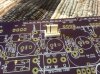
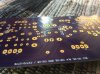
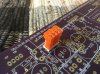
View attachment 1292187 View attachment 1292188 View attachment 1292189 The connector works
I pulled out pin 3 then eased it in, then straightened the pin.
Here are the picks.
Hope this helps and gives some options.
Cheers,
This connector will be added to the parts list. This connector is of a quality high enough to stand in place of the original.
I did not think it possible, but seeing is believing.
Thank you so much Bigbrive for going the extra mile to find this solution.

Last edited:
Ronito6
Super Member
View attachment 1292187 View attachment 1292188 View attachment 1292189 The connector works
I pulled out pin 3 then eased it in, then straightened the pin.
Here are the picks.
Hope this helps and gives some options.
Cheers,
Just a fitment suggestion to add here. Without soldering anything on, do a clearances check to make sure the connectors have enough space and that the positioning/orientation of the connectors are advantageous.
It is a minor thing, but it is good to make certain the connectors do not hit the card’s components or block the cards from being installed.
You are unlikely to have any problems I think, but...”A stitch in time...”.
Last edited:
Ronito6
Super Member
BIGDRIVE...Just to be certain. The connectors you ordered are this https://www.digikey.ca/product-detail/en/3-641208-4/A31678-ND/769821
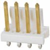
and this https://www.digikey.ca/products/en?keywords=3-641217-4-ND
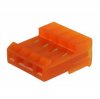
and this https://www.digikey.ca/products/en?keywords=3-641217-4-ND
Ronito6
Super Member
... pin 3 ...
One more point regarding that connector. Is it possible to accidentally plug that connector in reverse?
To avoid even the possibility of that sort of accident I would somehow block or seal the unused plug hole. Maybe super gluing a piece of plastic or whatever will fit to fill that void.
There will be a near zero chance of a reverse connection if you fill up that unused sector.
Last edited:
From an 'eyeball' at my own F-2772 upgraded X1, those 3 pin connectors are next to the MC Head Amps, just where the components happen to be resistors close to the board.Just a fitment suggestion to add here. Without soldering anything on, do a clearances check to make sure the connectors have enough space and that the positioning/orientation of the connectors are advantageous.
It is a minor thing, but it is good to make certain the connectors do not hit the card’s components or block the cards from being installed.
 It looks like the wires emerge from the connector from left to right, oriented with the connector as shown in post #32, which might cause slight difficulty with 'tall' electrolytic capacitors (i.e. C603).
Last edited:
slimecity
Super Member
I've almost finished populating mine, just waiting on one more set of caps - they should be here tomorrow.
Then over the next month I will remove the old one and start stripping links etc from it, to use for the new phono motherboard.
Unfortunately doing this comes in the middle of me doing general recon work on the remainder of the amp. Just finished reflowing and recapping the flat amp, reg powersupply board, muting board and protector boards.
I need to remove, recap & replace trimmers in both driver boards - and then she is 90% done - then I can start on the phono stage!
Kevzep reckons my MM boards are both OK, but I have issues with the MC boards. Hoping that wont equate to me trying to find some of those unobtanium FETs, thats for sure.....
Then over the next month I will remove the old one and start stripping links etc from it, to use for the new phono motherboard.
Unfortunately doing this comes in the middle of me doing general recon work on the remainder of the amp. Just finished reflowing and recapping the flat amp, reg powersupply board, muting board and protector boards.
I need to remove, recap & replace trimmers in both driver boards - and then she is 90% done - then I can start on the phono stage!
Kevzep reckons my MM boards are both OK, but I have issues with the MC boards. Hoping that wont equate to me trying to find some of those unobtanium FETs, thats for sure.....