Ronito6
Super Member
This posting is for the benefit of several AKers who recently acquired my F-2772 for their respective AU-X1's. I thought a single reference point would be the easiest way to answer questions and to share ideas.
Instructions for installing the new 2772 board into your X1.
PARTS LIST
Needed to complete the board.
6 x Omron G5V-2-DC24 signal relays.
1 x 33Ω ¼ watt resistor.
1 x 5.6Ω ¼ watt resistor.
3 x 1N4003 rectifier diode. (Replacing 10D1)
4 x 470µF 35V electrolytic capacitors. (I used 63V here)
2 x 0.047µF 100V film capacitors.
1 x 0.27µF 100V film capacitor.
Also, collect all wiring and hardware from your old broad too. You will use all of it on your new board.
(Parts list courtesy of Hyperion. http://audiokarma.org/forums/index.php?threads/replacing-au-x1-f-2772-phono-mother-board.833557/)
PREPARING THE NEW BOARD
First of all make sure that the corner mounting holes have been turned into ovals by either filing them down, or using a drill bit to grind them down, or by whatever means is easiest for you.
Doing this will guarantee that the board will lay flat against the chassis.
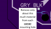
The distance required to file down can be seen by the white silk screen that marks where the holes are. Removing material to the point where the silkscreen indicates should be enough to allow the board to properly seat.
NOTATIONS
The board has notations for all wiring.
So where the wire originates and its destination point on the new board should be easily sussed.
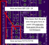
The board also has notations for all jumper wires.
NOTATIONS: CLEAR VS WHITE
The following should not be an issue for anyone swapping out an old version 2
Version 1 swappers should note:
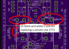
The stereo wires are encased in various colors of plastic, however the wires inside the casing will be either black and white, or black and clear.
Version 1 of the 2772 uses stereo jump wires that are black and white.
Version 2 of the 2772 board uses stereo jump wires that are black and clear.
MY NEW BOARD notations refers to these stereo wires only has black and clear.
So if you are installing my board to replace a version 1, please consider the word clear to mean white.
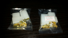
There are many of these…but here is a sample.

INSTALLATION ISSUES REPLACING A VERSION ONE
First remove all of the hardware and wires from the original board. You will need these parts to install into your new board.
NOTE:
The version 1 board uses a lot of tipped wires. I’ve designed my board with through holes large enough to receive these tips. So as long as you clean off the old solder from the wire tips, you should have no problem using the previous wiring from your version 1 on the new board.
NOTE: THE BIGGEST ISSUE FOR VERSION 1 REPLACERS - THREE PRONG HEADERS
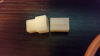
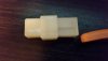
(Edit: Sep., 2018 - BIGDRIVE has found a suitable 3 prong header and plug. Examples and links for them are at the bottom of this posting. Also refer to posting #32.)
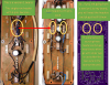
Sansui's original flawed 2772 design is fitted with two 6 pin headers.
Sansui's version 2 (the version upon which my board is based) uses just one 6 pin header, and two 3 pin headers. So one of the the 6 pin headers on the version 1 was redesigned into a pair of 3 pins headers on the version 2.
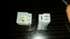
A picture to make the issue clear.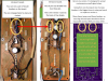
If you are lucky you have a Sansui parts pile where you can source the headers and the plugs that fit.
There is always directly soldering bare wire to pads, or addind solder lugs to which the bare wire would be soldered. Going with the bare wire/lug route is actually a superior solution in many ways. What you lose in modular design you gain in circuit integrity.
BUT if you wished to keep the modular design aspect, but wanted to use a modern solution there may be some other acceptable options.
For example one could wire in a pair of connector Molex connectors. If I did this I might consider running the wiring underneath the 2772. This would offer a way to hide the Molex plugs while placing out of the way all that wiring which normally crowds the phono cards .
INSTALLATION ISSUES REPLACING A VERSION TWO
This process for swapping out a version 2 ismore straightforward than replacing a version 1.
Original version 2s have all wiring and hardware necessary to make this board work.
(Most specifically the three prong headers and plugs.)
SOME LARGE THROUGH HOLES
The only problem you may encounter will be the size of some through holes for the jump wires.
On the original version 2, Sansui moved away from using the tipped wiring on the jump wires which they use in the version 1. On version 2 Sansui opted to go with bare wire jumpers.
So some through holes on my board may seem unusually large, but that was a compromise I intentionally incorporated to make things easier for those who opt to use the tipped jump wires from a version 1.
Of course ... version 2 folks can...
INSTALLATION
1. Before installing into the chassis, populate your board from the center out, going from the smallest components, jumper wires, and headers, up to the largest components.
2. Install the populated board into the chassis.
3. Finalize wiring the new board into the amplifier.
4. Reinstall your Phono and EQ cards
5. Check for shorts or other flaws or mistakes as you normally might.
6. Check all voltages and adjust them to spec if needed.
7. Enjoy your more stable X1, and the new small signal relays from this century.

https://www.digikey.ca/products/en?keywords=3-641217-4-ND

Instructions for installing the new 2772 board into your X1.
PARTS LIST
Needed to complete the board.
6 x Omron G5V-2-DC24 signal relays.
1 x 33Ω ¼ watt resistor.
1 x 5.6Ω ¼ watt resistor.
3 x 1N4003 rectifier diode. (Replacing 10D1)
4 x 470µF 35V electrolytic capacitors. (I used 63V here)
2 x 0.047µF 100V film capacitors.
1 x 0.27µF 100V film capacitor.
Also, collect all wiring and hardware from your old broad too. You will use all of it on your new board.
(Parts list courtesy of Hyperion. http://audiokarma.org/forums/index.php?threads/replacing-au-x1-f-2772-phono-mother-board.833557/)
PREPARING THE NEW BOARD
First of all make sure that the corner mounting holes have been turned into ovals by either filing them down, or using a drill bit to grind them down, or by whatever means is easiest for you.
Doing this will guarantee that the board will lay flat against the chassis.
The distance required to file down can be seen by the white silk screen that marks where the holes are. Removing material to the point where the silkscreen indicates should be enough to allow the board to properly seat.
NOTATIONS
The board has notations for all wiring.
So where the wire originates and its destination point on the new board should be easily sussed.
The board also has notations for all jumper wires.
NOTATIONS: CLEAR VS WHITE
The following should not be an issue for anyone swapping out an old version 2
Version 1 swappers should note:
The stereo wires are encased in various colors of plastic, however the wires inside the casing will be either black and white, or black and clear.
Version 1 of the 2772 uses stereo jump wires that are black and white.
Version 2 of the 2772 board uses stereo jump wires that are black and clear.
MY NEW BOARD notations refers to these stereo wires only has black and clear.
So if you are installing my board to replace a version 1, please consider the word clear to mean white.
There are many of these…but here is a sample.
INSTALLATION ISSUES REPLACING A VERSION ONE
First remove all of the hardware and wires from the original board. You will need these parts to install into your new board.
NOTE:
The version 1 board uses a lot of tipped wires. I’ve designed my board with through holes large enough to receive these tips. So as long as you clean off the old solder from the wire tips, you should have no problem using the previous wiring from your version 1 on the new board.
NOTE: THE BIGGEST ISSUE FOR VERSION 1 REPLACERS - THREE PRONG HEADERS
(Edit: Sep., 2018 - BIGDRIVE has found a suitable 3 prong header and plug. Examples and links for them are at the bottom of this posting. Also refer to posting #32.)
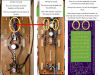
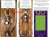
Sansui's original flawed 2772 design is fitted with two 6 pin headers.
Sansui's version 2 (the version upon which my board is based) uses just one 6 pin header, and two 3 pin headers. So one of the the 6 pin headers on the version 1 was redesigned into a pair of 3 pins headers on the version 2.
A picture to make the issue clear.
If you are lucky you have a Sansui parts pile where you can source the headers and the plugs that fit.
There is always directly soldering bare wire to pads, or addind solder lugs to which the bare wire would be soldered. Going with the bare wire/lug route is actually a superior solution in many ways. What you lose in modular design you gain in circuit integrity.
BUT if you wished to keep the modular design aspect, but wanted to use a modern solution there may be some other acceptable options.
For example one could wire in a pair of connector Molex connectors. If I did this I might consider running the wiring underneath the 2772. This would offer a way to hide the Molex plugs while placing out of the way all that wiring which normally crowds the phono cards .
INSTALLATION ISSUES REPLACING A VERSION TWO
This process for swapping out a version 2 ismore straightforward than replacing a version 1.
Original version 2s have all wiring and hardware necessary to make this board work.
(Most specifically the three prong headers and plugs.)
SOME LARGE THROUGH HOLES
The only problem you may encounter will be the size of some through holes for the jump wires.
On the original version 2, Sansui moved away from using the tipped wiring on the jump wires which they use in the version 1. On version 2 Sansui opted to go with bare wire jumpers.
So some through holes on my board may seem unusually large, but that was a compromise I intentionally incorporated to make things easier for those who opt to use the tipped jump wires from a version 1.
Of course ... version 2 folks can...
- use a larger wire gauge wire for the jump wires.
- or add tips to the jump wires
- or fold over the ends of the bare wiring culled from their original version 2. (the original bare wiring should then fill the through holes nicely.)
INSTALLATION
1. Before installing into the chassis, populate your board from the center out, going from the smallest components, jumper wires, and headers, up to the largest components.
2. Install the populated board into the chassis.
3. Finalize wiring the new board into the amplifier.
4. Reinstall your Phono and EQ cards
5. Check for shorts or other flaws or mistakes as you normally might.
6. Check all voltages and adjust them to spec if needed.
7. Enjoy your more stable X1, and the new small signal relays from this century.
- PLEASE SEE POSTING #16 BELOW IN HIS THREAD FOR PICTURES OF AND OTHER DETAILS REGARDING THE KUEHNE MODS.
- PLEASE SEE POSTING #32 IN THIS THREAD FOR DETAILS REGARDING CONTEMPORARY 3 PRONG CONNECTOR SOLUTIONS DISCOVERED BY BIGDRIVE.
https://www.digikey.ca/products/en?keywords=3-641217-4-ND
Attachments
Last edited: