• The move to the new server is done. There are some software and database maintenance updates in process. This has us passing the hat around to help out. We appreciate any donations. Seriously, even a dollar helps. The payment page may be found here - https://www.audiokarma.org/support.html

Introducing the Gillespie W-5M

Indeed. "Good enough" has taken over audio in a rather vicious way. I have no objection in principle to iPods, ear buds, and "docks" of various stripes. But I think there's an entire generation of folks who literally have no idea of how good HiFi can sound if you have the right setup. I myself have a fairly modest or at least mid-range rig, assembled over time, but it sounds very nice, and certainly WAY better than any iPhone/Pod dock.

Kim G

I'm trying to educate as many of the people in this generation, as possible. There will always be those that don't care to listen and learn- but many of them do seem to 'get it' after being exposed to "good" sound. And they don't want to go back to 'bad' sound afterward...

One of my best friends- he's about 15 years younger than me- has gone, from the time I met him to now, from a Sony HT receiver and a pair of "big box store" Yamaha speakers- to a Pro-Ject turntable, VAC integrated tube amp, and a pair of Von Schweikert Endeavor speakers, now. He says he can now hear what was so involving about those old LP records his parents and grandparents had. He has turned into a resource for new music for me- as he sometimes finds modern artists and albums, that I never knew to look for, on my own- things that sound great, and are recorded in high quality. It feels really rewarding to have my efforts come back to benefit me, that way...

Regards,
Gordon..
 
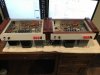
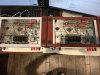
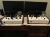
Well, after almost two additional years, I have twins! The second amp fired-up perfectly the first time. I transferred the tubes from the first to the second amp since they were known good, and all of the critical voltages were virtually identical to the first. It sounds fantastic as well. I still have a few things to wrap-up, but I'm glad to finally bring this project to a close. I have a pre-amp project under way to drive these. I would again like to thank Dave Gillespie for sharing his design! I can absolutely recommend this design to anyone looking for a unique project!

IMG_6443.JPG IMG_6444.JPG IMG_6446.JPG
 
I do tend to jump around a lot on projects - especially when I hit a roadblock on one and it's easier to look at something else while I mull over a solution to the other issue. :rolleyes:.

Actually, that's how professional techs work.

If your paycheck depends on items getting fixed- you can't afford to be sitting stuck on something for long. Hit a roadblock- something that just doesn't make sense- many times, the best option is to go to the next item- fix that, THEN come back to the first one.

Many times, by the time you've done something completely different in the meantime- the solution becomes almost self-evident. And in the time that you would have spent banging your head against the proverbial wall- you've actually been productive, and fixed something else...

Regards,
Gordon.
 
Would it make sense to use a 3-wire AC cord with ground prong, and earth the chassis for safety's sake?
I specifically asked Dave that question when I was designing the power supply. His answer was that a 3-prong power cord with grounded chassis is fine only if you intend to maintain separate AC ground from the audio signal ground. Since my chassis is connected to the signal ground (at the input jack only), I chose to use a 2-prong polarized plug. I used a 3-prong power cord on my first scratch-built amplifier project (a guitar amp), and I had constant buzzing issues requiring ground-lifts, etc., so I decided to not do it. You are correct that an AC grounded chassis would be safer, but there are literally millions of older pieces of equipment that do not have that feature.
 
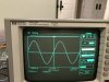
When I started this thread, I had promised some basic performance measurements when completed. Now that I have both amps finished, I feel like it's high time to make good on that promise. My testing efforts were hampered previously by a dying Hitachi oscilloscope and defective eBay purchases, but I did eventually fix the second Hewlett Packard purchased. Unfortunately, I was unaware of the way the newly introduced digital sampling scopes of the early nineties function, and let's just say, I don't like it. Even when you turn on the function to fill in the spaces between the dots, there is no such thing as a nice clear and smooth trace. Everything is full of jitter and you really have to study the pattern to see what's there.

Testing was performed with two 8Ω 50W non-inductive resistors in series across the 16Ω tap. I've seen Dave state several times that it's better to use the entire winding whenever possible, so I did.

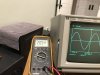
I started with a 1KHz sine wave at 4v rms (1 watt) measured at the output. Everything looked perfect, so I started bringing up the input signal while watching the sine wave for clipping. I started to notice the tops of the peaks flattening out at around 21 v rms, and then I backed it off slightly until they looked good. The voltage was 20.54v rms which calculates to 26.3 Watts. I see no crossover distortion in that pattern.

IMG_6472.JPG IMG_6474.JPG

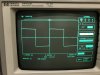
Next, I switched to a 1KHZ square wave with output power @ 1 Watt.

IMG_6475.JPG

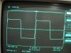
Then finally, a 10KHZ square wave @ 1 Watt.
IMG_6477.JPG


I'm no expert, but I'm pretty sure those are pretty nice square waves, indicating very nice high frequency response and stability. The jitter in the horizontal trace is not ringing, it's just outside the scope's capabilities to draw it any smoother. I see a slight amount of slant to the vertical trace compared to the 1KHZ pattern which appears perfectly vertical, which I guess is slew rate? There is a very slight overshoot at the transition to horizontal, and then immediate stabilization. I also see a very slight amount of rounding coming into the overshoot indication the high frequency response is just starting to taper off?

The set of used vintage output tubes in this amp appear to be very well balanced, and the dc balance pot is pretty much dead center. The pair in the other amp is quite the opposite. The dc balance pot is panned nearly full left to balance them out. I'm hoping to have a nice NOS set of Sylvania's soon and will report how that amp performs once I install them. I also plan to take frequency and voltage readings and plot out the power bandwidth which I will do next time also.

Looks like Dave worked his usual magic on this design :beerchug:, and as you can imagine, it sounds quite good.

Tom
 
Would it make sense to use a 3-wire AC cord with ground prong, and earth the chassis for safety's sake?
So, I've been thinking about your statement, and I'm considering doing this for at least a couple of reasons. I am finding that I really dislike the non-detachable cord, no matter how cool I think the black/white cloth covering looks. I also did some RTA frequency scans of one of the amps last night, and I'm seeing a significant 60Hz component with all the harmonics associated with it. I'm wondering if I have some ground looping going on with my test equipment. When connected to my music source, the amp seemed very quiet, although I could hear a faint buzz.

I had my internal audio ground bus connected to the chassis at a single point, so it was quite easy to remove that connection. I have ordered a couple of the standard 3-prong IEC-320 sockets with EMI filter to install. I figure I have three choices of how to finish this:

- Leave the audio ground disconnected from the chassis
- Connect the audio ground to the chassis using a "loop-breaker" type circuit
- Connect the audio ground to the chassis using a "loop-breaker" circuit and add a "ground lift" switch to allow disconnecting when needed

Any thought on what is best? Any suggestions on the best loop-breaker design? I guess it could be as simple as a single capacitor, but I've seen more elaborate using a pair of diodes, a resistor and capacitor - all in parallel.
 
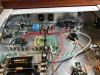
I completed the change on one of the amps tonight. I haven't tested yet to make sure it's still quiet, but will tomorrow. I did connect the audio ground to the chassis ground using a "loop breaker" circuit which consists of a 10Ω 5W resistor, two 1N5401 diodes, and a .1uF capacitor - all in parallel with the two diodes in opposite polarity. This connects between the single chassis ground point and the audio ground bus at the end with the HV center-tap. The concept is the audio ground will float above the chassis ground by 10Ω with any noise decoupled through the cap. Should the transformer short, the diodes will shunt to ground until the fuse blows or the diodes fail which usually means a full short to ground ensuring the fuse will blow.

IMG_6555.JPG IMG_6554.JPG
 
I completed the change on one of the amps tonight. I haven't tested yet to make sure it's still quiet, but will tomorrow. I did connect the audio ground to the chassis ground using a "loop breaker" circuit which consists of a 10Ω 5W resistor, two 1N5401 diodes, and a .1uF capacitor - all in parallel with the two diodes in opposite polarity. This connects between the single chassis ground point and the audio ground bus at the end with the HV center-tap. The concept is the audio ground will float above the chassis ground by 10Ω with any noise decoupled through the cap. Should the transformer short, the diodes will shunt to ground until the fuse blows or the diodes fail which usually means a full short to ground ensuring the fuse will blow.

View attachment 2515132 View attachment 2515133

Nice work on the amps, I just completed some w5m’s using the stock circuit myself. They may be my favorite amps.

did this help? I have a few amps that have a very minor buzz using extremely efficient jbl horn speakers but not really on any other speakers. But other amps do it in my house so I suspect it’s my houses 1950s wiring. Mine isn’t bad enough to hear so I just leave it alone.
 
Back
Top Bottom