• The move to the new server is done. There are some software and database maintenance updates in process. This has us passing the hat around to help out. We appreciate any donations. Seriously, even a dollar helps. The payment page may be found here - https://www.audiokarma.org/support.html

Introducing the Gillespie W-5M

tekuhn

AK Subscriber
Subscriber
Over a year ago, I was nearing completion of the transformation of my Fisher 400 receiver using the amazing modifications engineered by Dave Gillespie and I was already thinking ahead to what my next project might be. I have been holding onto a pair of the Altec-Lansing Peerless #16458 output transformers used on the Heathkit W-5M amplifier, just waiting for the right design for them. I reached out to Dave to see if he happened to have a circuit design that he recommended. His response, "Is there any reason that you don't just want to build the W-5M circuit?". I'm thinking that I imagine it's actually a fine amplifier, but was hoping that maybe Dave had something that he had fully scienced-out like his Dynaco SCA-35, Fisher 400, and several others that I've read about with amazement and great respect. Dave's next response was that he was indeed familiar with the #16458 OT's and that they were, in fact, very high quality pieces, but that his experience working with them was only in the context of the W-5M chassis.

Dave then proceeded to whet my appetite with the following statement:

"While the W-5M circuit is good enough, there are issues with it that left me feeling that it could be improved upon in a worthwhile way. What I ultimately ended up doing was converting the unit from a classic Williamson design, to a classic Mullard design, with very good results. Ultimately, the unit ended up using a 5AR4/GZ34 rectifier tube, 7027A output tubes (6L6GC or KT66 can still be used), a 6CG7 driver/inverter, and an EF86/6267 AF Amplifier stage. Besides lower distortion, greater stability, increased sensitivity, real power output is also increased somewhat as well. It does require the installation of a small -40 vdc power supply, but there's plenty of room to provide for that. If you're interested, I'll try and dig up my notes on the design.... Again, my experience with the 16458 transformer in developing the replacement circuit was entirely positive -- but that's the only experience I have."

I was hooked. And, by the way, he was remembering the details (without error) of a design that he did over 30 years ago in 1986!

Bear in mind that Dave's design is using an existing W-5M as the starting point, so it is not only using the 16458 OT, but also the 54-32 power transformer and the 46-12 7H 150ma choke. He also retained the basic design of the HV power supply, only adjusting the dropping resistors to achieve the necessary voltage changes. Since I did not have the PT or choke, I had to locate suitable replacements. The design I ultimately settled on uses a Dynaco P782 power transformer (reproduction), solid-state rectification, and a TV horizontal damper diode tube to provide the HV warm-up delay. I do expect the HV voltages to be a little lower and will update the schematic with the actual measured values once I have them.

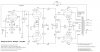
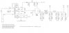
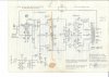
I will end this installment by providing Dave's hand-drawn schematic (with his permission) as well as one that I drew on the computer. Please understand that Dave has given me permission to share this project because I asked to do so for the benefit of those in the AK community who might like to try it and he readily agreed. Please respect Dave's intellectual work and ensure that he is given credit for the design if shared. I expect to have my first unit operational this week and will be providing a full detailed pictorial write-up of my build and also my impression of the performance. I do have some test equipment and will attempt to provide some limited, but hopefully meaningful measurements as well.

Tom Kuhn
Original Gillespie W-5M.jpg
7027A Amplifier.jpg
 
Register to hide this ad
Very interesting.
DC coupled EF86 6cg7 splitter fixed biased. Very elegant.
Thanks for sharing and thanks to Dave for sharing this too.
Brice.
 
Why the 1n4007 in the cathode circuit ?
After I worked out the power supply design, Dave suggested I add the diode. Here is his explanation.

The diode is a protection device, eliminating any timing concerns between the conduction times of the damper tube, and the driver tube. Without the diode, if the driver tube warms before the damper tube, then the driver tube will conduct the negative voltage of the inverter cathode supply up through the driver tube, out the plates and their resistor, and try to impress a negative voltage on the electrolytic cap supplying the inverter stage -- the polarity of the voltage impressed on the cap of course being opposite of the way (polarity wise) the electrolytic is connected into the circuit. To prevent any long term damage from happening from this scenario, the diode prevents the cathodes of the driver from ever going negative below ground. Once B+ is present, the cathode voltage rises to its normal positive value, and any possibility of damage is eliminated.
 
Last edited:
Here is the schematic for the power supply that I am using for my build. I researched as much as I could on the subject of grounding techniques and decided on a buss/star layout which means there are multiple star clusters attached to a common buss in a manner that tends to keep current flow isolated in zones to minimize ground loops. The numbers that I added to the ground connections on my main amp schematic and power supply schematic denote the star cluster assigned to it. I hope this all makes sense - this is my second scratch built amp and I am still very much learning the nuances of doing it well. I know there is much discussion on the subject of grounding, but this is what made sense to me.

The Dynaco P782 has a 117v primary. My line voltage is routinely 125v, so I decided to employ the unused the 5v secondary for bucking service as shown. I wanted to keep the 6.3vac heater voltage as close as possible to spec, otherwise I could have probably used the extra voltage on the B+ side to try to get as close as possible to the 550vdc design. The high voltage winding is rated at 200ma - considerably more than the 140ma of the stock W-5M PT. The supplier of this trans says it is capable of supplying 300ma continuously with only a 15v drop over 200ma. As I stated above, I wanted to overbuild to ensure a solid foundation for the amp.

In keeping with the overbuilt theme, I decided to use a pair of Heathkit chokes that I already had as well. They are massive 400ma-rated and have a DCR of just 38Ω. To give an idea of their size, they are potted in the same can that the W-5M power transformer uses. Heath advertises them at 5.5H. Mine measure close to 7H @ 120Hz using LCR meter. I'm guessing they will come in at at least 6H at 150ma.

As I said, I expect my B+ to come in lower than Dave's design using the stock W-5M power supply, however, I did power this up, and I measured 567vdc at the first filter network with no load.


7027A Power Supply.jpg

Ground Diag.png
 
Last edited:
After I worked out the power supply design, Dave suggested I add the diode. Here is his explanation. I suppose the scenario he is addressing could occur not just in my PS design, but with the standard W-5M PS as well...

The diode is a protection device, eliminating any timing concerns between the conduction times of the damper tube, and the driver tube. Without the diode, if the driver tube warms before the damper tube, then the driver tube will conduct the negative voltage of the inverter cathode supply up through the driver tube, out the plates and their resistor, and try to impress a negative voltage on the electrolytic cap supplying the inverter stage -- the polarity of the voltage impressed on the cap of course being opposite of the way (polarity wise) the electrolytic is connected into the circuit. To prevent any long term damage from happening from this scenario, the diode prevents the cathodes of the driver from ever going negative below ground. Once B+ is present, the cathode voltage rises to its normal positive value, and any possibility of damage is eliminated.
Thanks, now i understand.
 
Isn't the W-5M the one that is somewhat prone to losing it's power transformer anyway? Probably not a bad thing to use one thats got more capacity. Should give better regulation as well I'd expect, and thats never a bad thing.
Not just the power transformer, the overstressed Peerless opts also frequently died ugly. Finding one still potentially operational is a crapshoot in my experience. Rebuilding one as a lower powered Mullard makes a lot of sense with compatible output tubes.
 
Maybe I'm mixing apples and oranges.
I seem to remember someone recently working on a Mcintosh MC3500 ( or similar variant. There was an unusual fault which Dave solved with a diode. I suspect it was the scenario you described :thumbsup:
 
Maybe I'm mixing apples and oranges.
I seem to remember someone recently working on a Mcintosh MC3500 ( or similar variant. There was an unusual fault which Dave solved with a diode. I suspect it was the scenario you described :thumbsup:
I remember that too. Not sure of the details either, but I believe the OPs issue depended on what version of tube he used which I assume had faster or slower warm-up times.
 
I remember that too. Not sure of the details either, but I believe the OPs issue depended on what version of tube he used which I assume had faster or slower warm-up times.
MC3500/MI-350 series, similar warmup problem with individual tube samples causing atypical offset solved with a diode clamp like this, iirc.
 
Last edited:
Not just the power transformer, the overstressed Peerless opts also frequently died ugly. Finding one still potentially operational is a crapshoot in my experience. Rebuilding one as a lower powered Mullard makes a lot of sense with compatible output tubes.

FWIW- IME, it was the 16309 output transformer, used in the early Heath W5 amps, that was more fragile.

The 16458 was introduced to replace the 16309- and seemed to be more rugged. They could be killed- but they didn't sometimes die seemingly on their own, like the 16309 could....

The Dyna Mk II/ Mk III power transformer is an easy replacement for the W5 power transformer, though. Minor tweaking to voltage will be required (both the B+ and heater loads are less than what they are in the Mk III), but the basic starting voltages are very similar.

Regards,
Gordon.
 
I went back and re-read this thread - really great stuff and further support for why so many people, including myself, put so much stock in Mr. Gillespie's technical solutions and designs. He proves over and over again his amazing grasp of all things related to tube circuit design! I'm truly honored he shared his time and knowledge with me, because I know he is bound to be inundated with similar requests almost daily.
 
Unless I had loose Dyna OPTs, I'd be inclined to leave them in their amps and tidy those up.
I assume you were referring to the Heath OPTs being discussed? I ended up with the pair that I have when I bought a stereo homebrew amp at a hamfest swap meet 20 years ago. I didn't even attempt to power it up and simply parted it out and they've been sitting on the shelf ever since. I knew they were special and wanted to use them for my own project when the time was right. I agree - if I had a complete W-5M I'd build this on the existing chassis for sure.
 
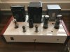
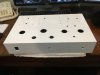
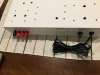
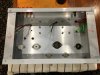
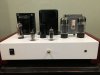
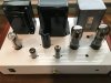
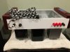
While I'm waiting on the parts I need to complete the amp, I thought I'd go ahead and share some pictures of the mechanical build. I purchased a pair of chassis' that I found on eBay. They are hand built in Killeen, TX. The metal is 1/8" aluminum and I don't remember the wood species, but I think it was from South America. The price was quite reasonable. They arrived with the aluminum polished which looked great, but I was afraid it would eventually oxidize, so I decided to try my hand at painting them using an automotive base/clear. After buffing, I was quite pleased with the result.

IMG_4046.JPG

IMG_4074.JPG

IMG_4072.JPG

IMG_4204.JPG

IMG_4211.JPG

IMG_4212.JPG
 
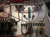
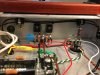
I used threaded standoffs attached to the existing bolts from the transformers and sockets to mount my terminal strips underneath the keep the top as clean as possible. I tried to layout the components in a logical way to keep wiring as short as possible and isolate the power supply from audio as much as possible. I'm sure there were better ways to do some of this, but I wanted to maintain a visual symmetry as well which probably compromised that slightly.

IMG_4214.JPG

IMG_4217.JPG

IMG_4240.JPG

IMG_5008.JPG

IMG_5010.JPG

IMG_5011.JPG
 
Back
Top Bottom