• The move to the new server is done. There are some software and database maintenance updates in process. This has us passing the hat around to help out. We appreciate any donations. Seriously, even a dollar helps. The payment page may be found here - https://www.audiokarma.org/support.html

Introducing the Gillespie W-5M

OK - I have some voltage readings. As I expected, my B+ is lower using the Dynaco PT (400v secondaries vs. 455v). Here's what I have:

HV prior to the damper diode: 523vdc
HV after damper: 517vdc
HV after choke at OT primary center tap: 513vdc
HV at 7027A plates: 500vdc
HV feeding the driver/splitter cathodes measured at AC balance pot center: 377vdc
HV feeding EF86: 244vdc
-40 supply: -39.02vdc
Heaters: 6.26vac

After running at moderate volume for over 30 minutes, the PT was barely above room temp - measured 95F. I think Dave has a winner here (also as expected :)). I've communicated my voltages to Dave and hope he will comment if any adjustments are needed at these operating points. I'd also like some suggestions on basic performance testing I can do. I have an oscilloscope and function generator.
 
After a side discussion with Dave on these voltage differences, I plan to remove the bucking circuit and assess where that shifts things. As long as the heaters stay under 6.615vac, I will likely do that and then also modify the value of the 6.8K dropping resistor to the driver/inverter stage to get that closer to the 425vdc design. I'll continue to provide updates, but I'm already considering this project a success and plan to start on the second amp soon. I appreciate all the input and most certainly appreciate Dave for the excellent design and support!

 
After a side discussion with Dave on these voltage differences, I plan to remove the bucking circuit and assess where that shifts things. As long as the heaters stay under 6.615vac, I will likely do that and then also modify the value of the 6.8K dropping resistor to the driver/inverter stage to get that closer to the 425vdc design. I'll continue to provide updates, but I'm already considering this project a success and plan to start on the second amp soon. I appreciate all the input and most certainly appreciate Dave for the excellent design and support!
I'm pretty sure the wood on your new cases is African Padauk. Beautiful material.

iu.jpeg
 
My old Hitachi oscilloscope is pretty much unusable. It was in storage for many years and even after trying to clean all the pots and switches (many are sealed) it is still very unstable and won't sync on any time/div setting. It was usable (barely) last year when testing the Fisher 400, but now it's not. Struggling with how much to spend and what to get. I guess no waveform testing for now. :(
 
analog scopes can often be had for small money. If its not digital, it ain't sexy, and people don't want them. My B&K was traded for a used laptop hard drive. The Tek scope came in a haul of a bunch of other stuff that I paid 50 bucks for.
 
I bought a GK Intek 620FG for $60, obviously some lab dispensing their old instruments. It works fine. I don't see any that cheap right now on eBay but the GK Inteks are usually portable and will serve your purposes fine. The Picoscope 2024 is about $120 without accessories and works very well, convenient to have screen captures and measurement features. It's signal generator only goes up to 100kHz so you'll need a better SG if you want to check for HF oscillations.
 
FWIW- IME, it was the 16309 output transformer, used in the early Heath W5 amps, that was more fragile. The 16458 was introduced to replace the 16309- and seemed to be more rugged...

Not wishing to take the attention from the details and beautiful craftsmanship @tekuhn has shared -- but hoping to gain some clarity on the timeline of Heathkit’s use of the 16309 and 16458 output transformers.

The general timeline which @GordonW suggested does seem to make sense -- in that an improved transformer would be used in the later amplifiers if there were reliability issues with the original transformer design in that application. It would come as no surprise that it would be physically larger for the same specifications and that it would have a higher part number - just as is done with later generations of tubes.

SO... what’s confusing to me o_O is this quote from Vacuum Tube Valley regarding the W-5M output transformer timeline. Vacuum Tube Valley never offered a correction -- in spite of several examples of offering corrections in subsequent issues when mistakes were made. Can this be an error that was overlooked?

Vacuum Tube Valley (Issue 2, Vol.1, pg 6):
"... Through 1957, W-5M's featured the larger Peerless 16458 output transformer. From 1957 through 1963, the newer design and smaller 16309 Peerless transformer was employed. Though more common, the 16309 is no slouch. It has exceptional characteristics and performance. Some Heath experts claim that the 16309 Peerless has more extended highs."

Hopefully I'm not too far off topic --

Can some Heathkit experts weigh in here?
 
After a bit more research it does appear that the Vacuum Tube Valley article on the W-5M is in error regarding the timeline of the transformers.

Culled from some older newsgroup postings from Mike LaFevre of Peerless\MagneQuest:

The 16309 was originally designed on February 10, 1955 by Ercel B Harrison.

The 16458 was originally designed for the Heath W5M amplifier (Heath part # 51-19) by E.B. Harrison on May 27, 1957.
 
I do remember finding reference to this in a thread somewhere, and it also mentioned the discrepancy, but the consensus was that the smaller 309 came first and was replaced by the 458.
 
I bought a GK Intek 620FG for $60, obviously some lab dispensing their old instruments. It works fine. I don't see any that cheap right now on eBay but the GK Inteks are usually portable and will serve your purposes fine. The Picoscope 2024 is about $120 without accessories and works very well, convenient to have screen captures and measurement features. It's signal generator only goes up to 100kHz so you'll need a better SG if you want to check for HF oscillations.
I won an auction for an HP Agilent 54501A this morning for $9.99. It fails self test for a NVRAM issue. I researched and this is a very common issue with this model series due to a Dallas NVRAM module failing after it's internal lithium battery dies. The part is still available (Mouser $24) and the repair involves desoldering a 28 pin DIP and replacing - socketing it, of course, like HP should have done. I'm pretty excited about the prospect of getting a pretty nice scope for cheap. The biggest expense is the $40 shipping, but should be all in for $75.
 
Congratulations on the scope!

This thread has moved my W5M restoration to the top of the list and got me thinking. These amps were originally designed for use with a WA-P2 pre amp and can often be found cheep or as a pair during the purchase. What if they were put into thogehter into a shared chassis/power supply? ie no umbilical cord as originally designed. Would they be Integrated Monoblocks? As the question relates directly to this amp I will ask it here.

This site and the web contain a couple of relevant posts about the use of the WP-2A. Overall it seems to be a fine preamp. Negative topics generally are limited to hum in the umbilical cord running the 120AC in parallel with the audio signal. Other comments discuss the circuits use of "loudness/volume control", and the possibility of overdriving the line input.

Mr Gillespie & TC Driver have posted in other threads about the WA-2P. for ease of refference I have linked them bellow.

Mr Gillespie's Post # 2 https://audiokarma.org/forums/index...ifi-dream-set-50-az-50-c.587557/#post-7733340
"In fact, your WA-P2 even uses the same circuit as the early 50C preamp does. The only difference is that the Fisher has its own power supply, and includes a loudness/volume control arrangement. Otherwise, they are identical, right down to the individual level controls, and four position EQ switches."

Mr Gillespie's post #3https://audiokarma.org/forums/index.php?threads/heathkit-wa-p2-pre-amp.429586/
"Hifi -- In terms of design, they use the typical Heathkit approach, employing a classic RCA phono preamp circuit (12AX7 with passive EQ), coupled with a Fisher style line/tone amp stage (another 12AX7 with passive tone controls). Besides the usual low output impedance at the main output jack that any good preamp offers, this preamp also offers a low output impedance at the tape out jacks, which most of the other main line kit manufacturers failed to offer back in the day.
The most notable failing of the design, is that the line/tone amp stage runs flat out all the time, with the main volume control placed between the output of these stages, and the main cathode follower output stage. While this approach makes for a very quiet preamp with the level control at minimum settings, it also means that the line level inputs can be easily overloaded. This fact was well documented in the press of the day. To address this issue, Heath provided individual input level controls on the back of the unit that are positioned before the line/tone amp stages in the circuit. You will need to make sure these individual input controls are adjusted to ensure that any line level signals you connect do not overload the line/tone amp stages to minimize distortion in the output.

Other than that, they require power from a power amp or external power supply to operate, and should respond well enough to the usual upgrades performed."

_______
TcDriver https://audiokarma.org/forums/index...ply-–-what-are-you-using.721788/#post-9731055

Lastly Mr Phil Nelson discusses this on his website:
https://www.antiqueradio.org/HeathkitWA-P2Preamplifier.htm

If a person were anticipating to restore both, a WA-P2 and a W5M would the combination prove beneficial?
 
I'll let the design experts comment - which I am not. It makes sense to me, though. Since the W-5M was designed to supply the necessary power to the pre-amp through the front octal socket, I guess it's safe to assume the W-5M power transformer will be up to the task - at least adequate. Would all those additional components fit on and in the existing chassis, or are you talking about a new chassis to house it all?
 
If you do build an integrated version, I'd consider adding a pair of RCA jacks on the back to serve as Pre-Out/Amp-In so that you can still separate them if desired. My guess is you could fashion a U-shaped jumper out of #12 copper wire if something like that is not available commercially.
 
Good idea, have you had a chance to start on the second amp?
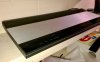
No, not yet. I'm still tweaking the voltages a bit and waiting on an oscilloscope so I can do some basic testing. Gadget73 planted the idea of mirror-imaging the other amp, which I really like that idea. Unfortunately I had already marked the other chassis and center-punched the holes. I think I'm still going to do it, but will have to fill all those divots.
 
Can you do it? Seems if you spend a little time now at this stage you will get what you want vs the rest of its life thinking what if.

Yes it was Gadgets idea that planted the seed for the combo. Plus, seeing your two Chassis sitting next to each other. My mind pictured the old B/O units. Remember the Bang and Olufen look. How about one unit ganged together. perhaps a dedicated power supply for the preamps and voltage regulation.
BEOCENTER 9000
B&0.jpg
 
Back
Top Bottom
