• The move to the new server is done. There are some software and database maintenance updates in process. This has us passing the hat around to help out. We appreciate any donations. Seriously, even a dollar helps. The payment page may be found here - https://www.audiokarma.org/support.html

Introducing the Gillespie W-5M

Are you talking about scoping the audio output, or looking at the B+ supply for any high frequency component riding on top of it?
Right, the rail feeds themselves. Balanced tube stages like p/p outputs have common mode rejection of power rail feed anomalies, but class 'A' stages typical of voltage gain stages don't, and can be affected by noise and such on the rail feed that the o'scope may show. Any signal impressed onto the power rails may affect the gain stages if not effectively bypassed.
 
I was talking about scoping the output to see if it affected stability margins.
Would you mind explaining stability margins and how to test that? I'm pretty new to the more technical aspects of this and would like to understand if it's not too lengthy to explain here.
 
Would you mind explaining stability margins and how to test that? I'm pretty new to the more technical aspects of this and would like to understand if it's not too lengthy to explain here.

Well, I'm pretty new to it too, as of last summer, thanks to the many experienced folks here. ;-) I can't do it the old-fashioned way, but I have a Picoscope (USB oscilloscope) that will run a Bode plot that compares the frequency response of the amp to the points where phase shifts occur in the high frequencies, and where those points threaten to intersect and create stability issues. Norman Crowhurst's "High Fidelity Circuit Design" is available with a google search, and it describes the issues involved. I'll post an example tomorrow.
 
I just read the Introduction - sounds like it's going to be awesome - thank you!

It's about as clear as it gets for a beginner. :). I've built a lot of basic, no-feedback SE designs before, but when I tried to figure out a PP feedback amp this really helped, even if I had to have a gadget do the work for me. ;-) The fact that he uses a basic Williamson as an example, the very amp I was trying to build, was a bonus.
 
Concerning the video above, unfortunately it’s probably difficult to write a mathematical representation of a tube amp’s transfer function so it’s difficult to use mathematical tools to determine gain and phase margin. It is however rather straightforward to test it with the actual amp on the bench, and you can determine rather quickly through a Bode plot what the actual amp stability characteristics are.

That being said, I don’t have tools to make Bode plots but I still know my amps are stable. You do this by trial and error testing on the bench, knowing for a transformer coupled tube amp, phase shifts approaching 180 degrees occur at the frequency extremes—down in the subsonic region and in the supersonic region. You then apply measures to either reduce phase shift, or reduce gain to less than unity, or both, at those frequencies, to force the amp into stability.

Control theory at large is a complicated subject and people get PhD’s in this stuff. For tube amps it’s rather straight forward once you know a few principles.

 
I only posted the video so that anyone reading Crowhurst or another article about phase shifts and feedback could understand what a Bode plot tells you. It took me a while to understand what I was supposed to look for in a Bode plot. It's no substitute for testing an amp but Picoscope's Bode plot generator is a handy tool and can at least help you spot potential problems.
 
I ran a couple of quick tests with and without the PS bypass caps and I don't see any difference in stability or HF phase shifts. As for HF components in the power supply, I don't know how to test for that, but I'll look it up. ;-)
 
hang the scope on the power supply, AC couple it, and see what you get. Should be some 120 hz ripple, and if its got any "fuzz" in addition to that, thats the HF noise. Prob want to use a coupling cap to keep a few hundred volts DC out of your scope probes.
 
Question about maximum voltages. My scope says 250V Max on the channel connectors. Does that mean with a 10X probe I can safely measure 2500 volts?
 
Last edited:
I'm going to leave the ripple measurements to someone else. :-/. From what I can find you need to build a DC blocking device with variable capacitor etc.
 
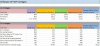
I've made my final adjustments to the power supply and it's been running for about 3 hours tonight. It sounds great! I still hope to do some waveform testing, but the good deal scope had another problem :(. After 3 hours the PT is warm, but not uncomfortable to touch - infrared scanner says it's 122F . Absolutely no bad behavior that I can see at this point. It is very sensitive and will buzz if the input is open. With a shorting plug or connected to a source, it is very quiet. I hear nothing in the horn and a very slight buzz in the woofer. Once I get the scope working I can hunt that down.

Here are the final schematics and my test voltages:

Gillespie W-5M.jpg

PS for Gillespie W-5M.jpg

Voltages.jpg
 
I'm curious how the regulation is affected at full output from bucking, no bucking, and with the extra CL-80. I suspect with the extra thermistor will make things worse but thats just a hunch.
 
Back
Top Bottom