

You are using an out of date browser. It may not display this or other websites correctly.
You should upgrade or use an alternative browser.
You should upgrade or use an alternative browser.


That's a very interesting idea which I had not thought of. The other chassis is already taped-up and I have center punched the holes, but nothing is drilled. I would have to sand and fill those which is certainly doable. I do like the thought of that visually. I will give that some thought!are you planning to mirror image the amps?

I used threaded standoffs attached to the existing bolts from the transformers and sockets to mount my terminal strips underneath the keep the top as clean as possible. I tried to layout the components in a logical way to keep wiring as short as possible and isolate the power supply from audio as much as possible. I'm sure there were better ways to do some of this, but I wanted to maintain a visual symmetry as well which probably compromised that slightly.
View attachment 1716889
View attachment 1716893
View attachment 1716894
View attachment 1716906
View attachment 1716907
View attachment 1716914
Those chassis are the proverbial bomb. I've used several of them myself, and will continue to do so. Horace is a great guy to deal with!
Regards,
Gordon.
Totally agree - the fit and finish was first rate.Those chassis are the proverbial bomb. I've used several of them myself, and will continue to do so. Horace is a great guy to deal with!
Regards,
Gordon.

Very nice layout and construction underneath and love the color choice. Where did you get those terminal strips with the U shaped terminals?
Thank you! The terminal strips came from Tube Depot. I buy the long ones and just cut to length. You can remove contacts by drilling out the rivet.Very nice layout and construction underneath and love the color choice. Where did you get those terminal strips with the U shaped terminals?

CA2010
Member
The metal is 1/8" aluminum and I don't remember the wood species, but I think it was from South America. The price was quite reasonable. They arrived with the aluminum polished which looked great, but I was afraid it would eventually oxidize
Regarding your chassis. Just a quick thought.. . By no means do I wish to steer your post into a lengthy discussion on chassis refinish but thought to share a product link. Here is a link suggested by another AK'er (my apologies to the original poster, I lost the info of its original author) but here is the link. It is a clear coat for aluminum. Perhaps others can comment performance. My 1st can for testing is on order.
Not suggesting its use over your choice, rather another tool for the future. Your work is very impressive and I think it looks terrific.
Cerakote aluminum finish. (no affiliation, heck I have not even tried it yet but it seems like a good option)
https://www.cerakote.com/finishes/M...qh-HygrWqySKPT5UmxXTR_mBSEkg1f68aApOqEALw_wcB
Last edited:
That name sounded really familiar and I had to poke around on their website before I realized why - Cerakote has an excellent reputation as a tough firearm coating. I appreciate the suggestion. I was very tempted to go with the polished aluminum - it looked awesome, but I was worried it would begin to oxidize (it would) and would be tough to maintain. This sounds like a good solution.Regarding you chassis. Just a quick thought.. . By no means do I wish to steer your post into a lengthy discussion on chassis refinish but thought to share a product link. Here is a link suggested by another AK'er (my apologies to the original poster, I lost the info of its original author) but here is the link. It is a clear coat for aluminum. Perhaps others can comment performance. My 1st can for testing is on order.
Cerakote aluminum finish. (no affiliation, heck I have not even tried it yet but it seems like a good option)
A few comments about my build:
1) I was not able to source a 300Ω 5W pot for the DC balance control. I was going to use a 250Ω pot with a 25Ω resistor on either side to maintain the same overall resistance but knowing it would lessen slightly the range of adjustment. Dave said it was fine to substitute the 250Ω and there was no need to add the 25Ω resistors - so that's what I did. The stock W-5M already has this pot, so if you're modifying an existing chassis then you already have the right part.
2) The cap can that you see on my chassis is a quad 40-20-20-20. I was initially planning to use the individual sections as the last filter cap in the series filter strings for each voltage take off. However, once I worked out my grounding I realized that the shared common would prevent me from grounding each filter network using separate star clusters. The chassis was already drilled and the can mounted, so, I ended up paralleling all 4 sections and using it for the final 100uf filter on the -40 supply. Obviously a 100uf @ 63v would suffice for that application and easily mount inside the chassis and have cost a lot less money. Lesson learned. And yes, the cap can body is at -40 referenced to ground, but I have it painted and might consider some clear heatshrink on it as well if it doesn't look too bad. The cap is after the dropping resistor in the circuit and I calculate the maximum current draw at a dead short is only 22ma. Nobody wants to feel that tingle when you touch an operating amp, but it's certainly not a health hazard.
3) The solid-state rectifiers I used are ultra-fast, soft recovery HEXFREDs. Vishay VS-HFA08PB120. I know that is a subject of much discussion, but I have read that they are "quieter" and can help in providing cleaner power to the amp. More importantly, I was trying to minimize voltage drop since my PT has a lower HV winding that the stock W-5M and I want to get as close as possible to the design voltage.
4) I used Jantzen Superior Z-caps for the coupling caps. Again, much discussion about whether caps can actually color or influence the sound. I don't have enough experience to have an opinion one way or the other, but these sound like a high quality part and I found someone selling them cheap on eBay so in they went.
5) When comparing Dave's schematic with the stock W-5M schematic, you will notice that the output transformer primary leads are swapped. I noticed that and asked Dave whether it made any difference. He reminded me that since his design has one less gain stage, the swap is necessary to keep the phasing correct for the negative feedback signal. In his words - "You better believe the lead color matters! If you reverse them from that shown, the negative feedback becomes positive feedback, turning the power amplifier into a power oscillator!" LOL - I'm glad he is patient with me because I know I have asked a lot of questions that the answers are obvious to the more experienced.
6) I'm wondering if I should have drilled some ventilation holes around the damper and power tubes. The chassis bottom cover is perforated, but without holes in the top of the chassis to allow some sort of convection flow, I worry about high temps inside the chassis and around the hotter tubes.
7) I asked Dave whether this design could benefit from a form of his EFB(tm) circuit. His response - "Once the unit is built and you test it, measure the B+ voltage when the amplifier is driven from quiescent, to full power output. I doubt that it will change very much, meaning that EFB will do little if any good in this case. Of course, testing will prove that out one way or another, but I'm comfortable that will be the result."
8) Since I am building a pair of these for stereo use, I wondered if it was important to keep the phasing of all the A/C power windings the same for each amp to ensure there was no weird phase interaction or cancellations if the two amps were somehow out of phase with each other. Dave pointed out that after rectification, any A/C pulses present are at 120Hz and therefore in phase even if the power cord is reversed in the socket. I did note however that the -40 is derived from 1/2 wave rectification and potentially could have pulses 180 off from the other amp. I feel sure I'm nit-picking, but to be sure each will be wired exactly the same in all aspects, I used a 9v battery and a very sensitive mechanical meter and pulsed power to the PT primaries and determined a "positive" lead for each winding of the PT to establish it's phasing. This will allow me to wire each amp in an identical manner, and that, in conjunction with a polarized 2-prong power cord will ensure both amps are operating the same in all respects.
1) I was not able to source a 300Ω 5W pot for the DC balance control. I was going to use a 250Ω pot with a 25Ω resistor on either side to maintain the same overall resistance but knowing it would lessen slightly the range of adjustment. Dave said it was fine to substitute the 250Ω and there was no need to add the 25Ω resistors - so that's what I did. The stock W-5M already has this pot, so if you're modifying an existing chassis then you already have the right part.
2) The cap can that you see on my chassis is a quad 40-20-20-20. I was initially planning to use the individual sections as the last filter cap in the series filter strings for each voltage take off. However, once I worked out my grounding I realized that the shared common would prevent me from grounding each filter network using separate star clusters. The chassis was already drilled and the can mounted, so, I ended up paralleling all 4 sections and using it for the final 100uf filter on the -40 supply. Obviously a 100uf @ 63v would suffice for that application and easily mount inside the chassis and have cost a lot less money. Lesson learned. And yes, the cap can body is at -40 referenced to ground, but I have it painted and might consider some clear heatshrink on it as well if it doesn't look too bad. The cap is after the dropping resistor in the circuit and I calculate the maximum current draw at a dead short is only 22ma. Nobody wants to feel that tingle when you touch an operating amp, but it's certainly not a health hazard.
3) The solid-state rectifiers I used are ultra-fast, soft recovery HEXFREDs. Vishay VS-HFA08PB120. I know that is a subject of much discussion, but I have read that they are "quieter" and can help in providing cleaner power to the amp. More importantly, I was trying to minimize voltage drop since my PT has a lower HV winding that the stock W-5M and I want to get as close as possible to the design voltage.
4) I used Jantzen Superior Z-caps for the coupling caps. Again, much discussion about whether caps can actually color or influence the sound. I don't have enough experience to have an opinion one way or the other, but these sound like a high quality part and I found someone selling them cheap on eBay so in they went.
5) When comparing Dave's schematic with the stock W-5M schematic, you will notice that the output transformer primary leads are swapped. I noticed that and asked Dave whether it made any difference. He reminded me that since his design has one less gain stage, the swap is necessary to keep the phasing correct for the negative feedback signal. In his words - "You better believe the lead color matters! If you reverse them from that shown, the negative feedback becomes positive feedback, turning the power amplifier into a power oscillator!" LOL - I'm glad he is patient with me because I know I have asked a lot of questions that the answers are obvious to the more experienced.
6) I'm wondering if I should have drilled some ventilation holes around the damper and power tubes. The chassis bottom cover is perforated, but without holes in the top of the chassis to allow some sort of convection flow, I worry about high temps inside the chassis and around the hotter tubes.
7) I asked Dave whether this design could benefit from a form of his EFB(tm) circuit. His response - "Once the unit is built and you test it, measure the B+ voltage when the amplifier is driven from quiescent, to full power output. I doubt that it will change very much, meaning that EFB will do little if any good in this case. Of course, testing will prove that out one way or another, but I'm comfortable that will be the result."
8) Since I am building a pair of these for stereo use, I wondered if it was important to keep the phasing of all the A/C power windings the same for each amp to ensure there was no weird phase interaction or cancellations if the two amps were somehow out of phase with each other. Dave pointed out that after rectification, any A/C pulses present are at 120Hz and therefore in phase even if the power cord is reversed in the socket. I did note however that the -40 is derived from 1/2 wave rectification and potentially could have pulses 180 off from the other amp. I feel sure I'm nit-picking, but to be sure each will be wired exactly the same in all aspects, I used a 9v battery and a very sensitive mechanical meter and pulsed power to the PT primaries and determined a "positive" lead for each winding of the PT to establish it's phasing. This will allow me to wire each amp in an identical manner, and that, in conjunction with a polarized 2-prong power cord will ensure both amps are operating the same in all respects.
Last edited:

Looks like it's going to be a nice pair of amps when you are done. I've used those chassis before also and they are keepers. The white looks good.
Concerning phasing of AC inlet wires, inlet phasing doesn't matter because the diodes can't tell which orientation is which. The output of the rectification stage produces 120 Hz ripple anyway, and that ripple looks identical in either inlet phase orientation. But it takes zero effort to wire both amps the same, and you'll sleep better at night knowing your OCD itch has been scratched.
Concerning phasing of AC inlet wires, inlet phasing doesn't matter because the diodes can't tell which orientation is which. The output of the rectification stage produces 120 Hz ripple anyway, and that ripple looks identical in either inlet phase orientation. But it takes zero effort to wire both amps the same, and you'll sleep better at night knowing your OCD itch has been scratched.
LOL - exactly right!........you'll sleep better at night knowing your OCD itch has been scratched.

Thank you, and sure.... The seller goes by hma60 and is located in Killeen, TX. I paid $90 shipped for each chassis. I never communicated with him outside of eBay, but it sounds like GordonW has and might be able to provide better contact information. It did take longer to deliver than advertised, but the product delivered was worth the wait and I'm pretty sure they are custom made to order. My chassis is 16"x10"x3".

May I ask why mono? do you listen to mono a lot?
I think he finished one channel and is testing it. ;-)
These are very nice, BTW.
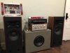
Zack is correct - I'm building a pair, but only did one so I could make sure I liked it before building the other. It is sounding very good indeed!May I ask why mono? do you listen to mono a lot?
I'm using one pre-out channel of a Pioneer SA-9900 to drive the amp and the other channel playing through the Pioneer. In comparison, the new amp is louder (more sensitive, less power obviously). The Pioneer seems to have a little more bass extension, but is noticeably lower in midrange which the new amp has which adds a noticeable presence to vocals.
Last edited: