• The move to the new server is done. There are some software and database maintenance updates in process. This has us passing the hat around to help out. We appreciate any donations. Seriously, even a dollar helps. The payment page may be found here - https://www.audiokarma.org/support.html

Introducing the Gillespie W-5M

I'm curious how the regulation is affected at full output from bucking, no bucking, and with the extra CL-80. I suspect with the extra thermistor will make things worse but thats just a hunch.
Good question. I haven't taken it to full power yet. Is there a safe way to do it without a scope? Dave says I will be down on max power slightly with the lower B+ than his design. I'm guessing 22 watts is reasonable. I have a pair of 8Ω 50W non-inductive resistors I can put on the 16Ω tap in series. What type of signal should I use - 1KHz sine wave? Can I just bring the input signal up until I have about 20 watts on the load? Does standard math apply here? 20W on 16Ω = 17.88volts @ 1.19amps? If that is safe to do, I'll bring it up to 20W and monitor the B+.

Each CL-80 is dropping the line by 2 volts. Is your hunch that it's voltage drop is not linear with current flow?
 
Last edited:
Researching the CL-80 device, it's resistance decreases as current increases (temperature rises). I guess I have no idea how rapidly this resistance change occurs, but in a way, I could see this actually helping with regulation if it occurs fast enough.
 
a scope to see were it starts clipping is ideal, but you can just wind it up to some reasonable but not excessive power level to get an idea what the regulation does. 10-15 watts would probably be enough.
 
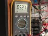
Just ran a test. I input a 1KHz sine wave and drove the 16Ω load to 12.65 volts which I calculate is 10W. The B+ measured at the choke output (OT center tap) was 528vdc at idle and 527vdc at 10W output. I don't know if it will behave differently with a more dynamic input signal (music), but I think the result is encouraging. It required a .69vac input signal to drive it to 10W out. Dave's schematic indicated he measured .425vac for full output. Is this difference due to the type of signal I'm using, perhaps?

IMG_5041.JPG

IMG_5040.JPG
 
thats very good regulation if it only dropped a volt. You should be in really good shape with actual music. I rather like stout supplies, it tends to make for a nice clean sounding amp.

shouldn't have anything to do with the waveform, I'm guessing Dave probably did that measurement with a sine wave. That much difference in input sensitivity might indicate a difference in feedback level or open loop gain though.
 
...That much difference in input sensitivity might indicate a difference in feedback level or open loop gain though.
It seems I either don't understand, or can't trust the "Amplitude" value indicated on the wave generator display. I re-ran the test and piggy-backed my voltmeter onto the input and with the generator indicating .700v, the actual measured a/c voltage was .250v. That is very much in line with expectations. I get the same result if I disconnect the leads from the amp and simply measure the output of the generator - .700v indicated = .250v measured.
 
It seems I either don't understand, or can't trust the "Amplitude" value indicated on the wave generator display. I re-ran the test and piggy-backed my voltmeter onto the input and with the generator indicating .700v, the actual measured a/c voltage was .250v. That is very much in line with expectations. I get the same result if I disconnect the leads from the amp and simply measure the output of the generator - .700v indicated = .250v measured.

I think I know what's going on.

The signal generator is likely giving a reading of PEAK TO PEAK voltage- while the meter is reading in RMS volts.

If you start with 0.700v- cut that in half (peak, instead of peak-to-peak), that's 0.350v.

Then, do the conversion to RMS volts (which is 0.707 times peak voltage), and you get 0.247v.

That's too close to be coincidental, I think.

Regards,
Gordon.
 
I think I know what's going on.... Then, do the conversion to RMS volts (which is 0.707 times peak voltage), and you get 0.247v.

That's too close to be coincidental, I think.

Regards,
Gordon.
Sounds logical to me. I’m trying to find documentation on the function generator, but not having success yet. It was a fairly inexpensive Chinese item.

I thought I could trust the displayed value because it agreed exactly with my semi-functional oscilloscope. But, I reckon the scope would be displaying p-p also though since I was looking at the value of the PEAKS :D.

My meter is true RMS. Thanks for the explanation!
 
I never did ask Dave how he provided the -40 cathode supply in his build, but you'll need to address that. My PT had a 55v bias tap on the HV winding so I used that. That 250ma HV winding awesome and at 450-0-450 will work great with GZ34 as his design specifies. No center tap on the larger 6.3 though.
 
I assume the 6.3 center tap is connected to power tubes cathodes to keep the cathode to heater potential in spec. You should be able to use the 2A winding to them and the 4A for the others.
 
I assume the 6.3 center tap is connected to power tubes cathodes to keep the cathode to heater potential in spec. You should be able to use the 2A winding to them and the 4A for the others.
Actually, if you want to be able to try KT66's, they require 1.3A each for heater, so the 2A winding won't be enough. I have seen a false center tap constructed by attaching a pair of series resistors across the winding and connecting to the center of them. I don't know if that would work here, or what value resistors to use, but I have no doubt Dave and others will know a solution to this.
 
Thank you for the suggestion, I do have several other stock PT's from W5M I'd like to use. It was just a nice surprise to see this in the chassis, the 250ma made me smile. Gonna save this one for a different project. (Unknown at this time. ideas always welcome) Please forgive if this is braggadocios and sounds bad, but other happy news to share, After many many many months of waiting and searching our local sites I was able to find and buy a nice pair of forte II speakers this weekend. There is fun in the journey, Getting closer!
 
Congrats on the Forte's !

Thanks! I"ve got to be honest, I'm not familiar with having an additional winding on the primary side in this case the 6.3 a 4a. Does this function the same as if it were on the secondary? Is it on the secondary? Would some one please point me in the right direction.
 
Here is the 54-32 Power transformer Schematic from the W5M assembly manual. Daves schematic starts at the choke. Would anyone be comfortable explaining how to supply the --40 cathode supply using this PT.

w5m PT Schematic.JPG
 
Back
Top Bottom