

You are using an out of date browser. It may not display this or other websites correctly.
You should upgrade or use an alternative browser.
You should upgrade or use an alternative browser.
Is your unobtainium power switch worth $5 and an hour or so of your time?
- Thread starter K7sparky
- Start date
![mains schematic [factory].png](/forums/data/attachments/3671/3671723-623bc7435815353fbe833ca166ea130c.jpg?hash=mTX_mx1IZ3 "mains schematic [factory].png")

Raccoon1400
Super Member
No. The power switch goes between the gate and A2 side.Here is my proposed rendition for a Yamaha CA-610 II, before / after. Looks OK?
View attachment 3797699View attachment 3797700
Better to use the part recommended in original post too, more current headroom.
Thanks for your response. I did notice the switch was connected to the A2 side on several of the diagrams floating around and I'm not getting why.No. The power switch goes between the gate and A2 side.
Intuitively it seems you'd want the gate switch connected to the hot side where there's voltage to apply to the gate and fire the triac when you close the switch. There's just no voltage on the A2 side, until the triac fires.
If the correct way is to connect the switch to the A2 side then I'm missing something and / or not understanding the way triacs work. It would be helpful if you could briefly explain why switching on the A2 side works and switching on the A1 side does not. Thanks!
The BTA12-800BWRG is rated 12A continuous and 120A surge... Neither normal power consumption nor inrush current would likely come near.Better to use the part recommended in original post too, more current headroom.
Here is my test setup, with triac at center:

Triac is connected as follows ('A1' and 'A2' is the terminology STMicro uses in their datasheet instead of the more common 'MT1' and MT2'):
- Hot (black) to A1
- Load (red) to A2
- Switch leg: Green to gate, yellow to A2 per recommendation above in post #662

Triac is connected as follows ('A1' and 'A2' is the terminology STMicro uses in their datasheet instead of the more common 'MT1' and MT2'):
- Hot (black) to A1
- Load (red) to A2
- Switch leg: Green to gate, yellow to A2 per recommendation above in post #662
Last edited:
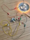
However, when I moved the switch leg (yellow) to A1 (i.e. the way I originally had it post #661) closing the switch did not turn on the light.
Therefore, switch leg to A2 is indeed the correct configuration.
Which is fine, but my question was why?
The only way this makes sense is if the gate is energized while the triac is off, so that closing the switch allows current to flow out of the gate. Then you would want the switch leg to terminate at the load side.
And sure enough, there's 120V between A2 and gate when the switch is open:
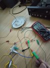
Dropping to 18 mV when the switch is closed and the light is on:

Therefore, switch leg to A2 is indeed the correct configuration.
Which is fine, but my question was why?
The only way this makes sense is if the gate is energized while the triac is off, so that closing the switch allows current to flow out of the gate. Then you would want the switch leg to terminate at the load side.
And sure enough, there's 120V between A2 and gate when the switch is open:
Dropping to 18 mV when the switch is closed and the light is on:
Last edited:
![mains schematic [triac mod].png](/forums/data/attachments/3672/3672763-0e39de245afc963afb2f04c5fafd7d67.jpg?hash=-d1QKGdq_9 "mains schematic [triac mod].png")

Agreed.I usually connect the switch-resistor-gate array directly to the AC line, not through the transformer
But US-market vintage gear generally has non-polarized plugs, making that connection a crapshoot, with gear as likely to be switched on the neutral as on the hot (as it should be), depending on the direction the plug was inserted.
To avoid this, this amp is getting a new polarized power cord.
Do you consider it a safety concern to keep the triac on the hot side? My understanding is it will work either way. If you go polarized don't you give up the option to reverse to reduce turntable hum?To avoid this, this amp is getting a new polarized power cord.
Switching on the neutral works in terms of functionality; so does a Chicago three-way, but you wouldn't want one in your house 
None of these things are a direct safety risk as long as nothing goes wrong.
As far as flipping the plug to reduce hum, chances are the hum will be lowest in the correct polarity position anyway. In any event, it's best to diagnose and fix the grounding fault.
None of these things are a direct safety risk as long as nothing goes wrong.
As far as flipping the plug to reduce hum, chances are the hum will be lowest in the correct polarity position anyway. In any event, it's best to diagnose and fix the grounding fault.

Switching on the neutral works in terms of functionality; so does a Chicago three-way, but you wouldn't want one in your house
Funny you should mention that. I encountered one of those in a farmhouse constructed in the early 1920s which used that scheme on two staircases. It took me the better part of an afternoon to decipher just exactly what was going on there and why none of the wiring had the voltages that made any sense. Once it became clear, I remembered the scheme from my 1970s training, but had NEVER encountered a real-life Chicago (a.k.a. "Carter") arrangement for 50 years.
Agreed.
But US-market vintage gear generally has non-polarized plugs, making that connection a crapshoot, with gear as likely to be switched on the neutral as on the hot (as it should be), depending on the direction the plug was inserted.
To avoid this, this amp is getting a new polarized power cord.
Another avoidance technique is to round-bin the idea of a triac and install a relay that will not create line/crossover noise, will not alter the AC incoming waveform, and will not expose the switch to any potential high load if the device fails.
Thanks for the replies:
It's nothing like the Chicago three way is it, that implies you can grab a virtually non current limited 120VAC per its design?
Worst case scenario from what i can find with a flipped plug is the hot goes to chassis through a 2.2 meg resistor, which is how it was designed. Maybe you are visualizing the Triac failing where it shorts to chassis so the chassis would become hot?
Did you tie neutral to chassis or add a safety ground when you installed the polarized plug?
I agree, but diagnosing could be as simple as flipping the plug could it not? What are you trying to accomplish here - to get different chassis at equal potentials so no current flows through the RCA cable shields between units. I guess i was thinking Marantz and other manufacturers built it this way for a reason.
The original poster included waveforms of the transformer supplied power and I didn't see anything that suggested there was line crossover or it was altered. Do you have something you could share please?
Even a catastrophic fail of the Triac worst case is 170volts peak / 100 ohms or 1.7 amps, so well below what the switch is rated for and would not last long as the resistor would open. Did you have another thought on how the Triac would overcurrent the swtich?
Switching on the neutral works in terms of functionality; so does a Chicago three-way, but you wouldn't want one in your house
It's nothing like the Chicago three way is it, that implies you can grab a virtually non current limited 120VAC per its design?
Worst case scenario from what i can find with a flipped plug is the hot goes to chassis through a 2.2 meg resistor, which is how it was designed. Maybe you are visualizing the Triac failing where it shorts to chassis so the chassis would become hot?
Did you tie neutral to chassis or add a safety ground when you installed the polarized plug?
In any event, it's best to diagnose and fix the grounding fault.
I agree, but diagnosing could be as simple as flipping the plug could it not? What are you trying to accomplish here - to get different chassis at equal potentials so no current flows through the RCA cable shields between units. I guess i was thinking Marantz and other manufacturers built it this way for a reason.
Another avoidance technique is to round-bin the idea of a triac and install a relay that will not create line/crossover noise, will not alter the AC incoming waveform, and will not expose the switch to any potential high load if the device fails.
The original poster included waveforms of the transformer supplied power and I didn't see anything that suggested there was line crossover or it was altered. Do you have something you could share please?
Even a catastrophic fail of the Triac worst case is 170volts peak / 100 ohms or 1.7 amps, so well below what the switch is rated for and would not last long as the resistor would open. Did you have another thought on how the Triac would overcurrent the swtich?
Nothing beyond what you detailed. However, considering that the entire thread is related to an already compromised switch that potentially cannot sustain the 70W standby current without making dial lamps flicker and power supplies to sag, 1.7A (1,700 mA) is a far cry from the worst-case scenario of a relay coil demanding up to 35mA to hold the armature closed, by well over an order of magnitude.