• Please note that Audiokarma will be offline briefly for updates early on Monday morning, September 28th.

Isolated the hum

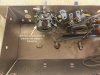
Here are some pics, starting with the amp, and then the pre amp. If these aren’t good enough quality, let me know and I can take more.

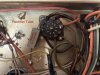
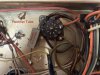
The filter can I used only covered C1 A-C, so there is a standalone cap for C1D (Cathode). Two wires (yellow and yellow-green striped) connect to the positive side of C1D, negative side is grounded to a grounding tab on the can (white wire).
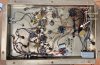
FD0D9612-4FB9-43B2-A421-44FB4881DEE0.jpeg

Two ceramic caps associated with the center channel that are out of tolerance circled in red.
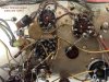
5323A13D-C748-4C3C-8F38-C0D863DB8A59.jpeg

0B85E54F-3D77-4011-9031-3B6DA5155B20.jpeg

Part 1 of 3 of the pre-amp - two out of spec caps circled
30F5D7A2-FD66-4349-B6C0-0F466940130B.jpeg

Preamp 2 of 3
Orange electrolytic caps replaced last year - all ceramic caps in view tested outside of tolerance.
29D5A74E-501F-400C-8554-E23094156285.jpeg

Preamp 3 of 3
2859CFE5-5357-41F7-AD5D-0316A5974787.jpeg
 
I'd move that cathode cap a lot closer to the output tubes. Honestly not much reason for it to not be attached right at the socket across the resistor. Just space it off the resistor enough so it doesn't get so hot. The long wire leads to that across the AC wiring probably aren't doing it any favors for noise pickup, though in theory the cap should be shunting that to ground. If you really want to keep it grounded to the original spot, I'd solder the cap - direct to the original location and run the wire from tubes to cap diagonal across the chassis like it probably ran originally.

Did we ever establish if this is quiet with the inputs shorted to ground ?
 
I'd move that cathode cap a lot closer to the output tubes. Honestly not much reason for it to not be attached right at the socket across the resistor. Just space it off the resistor enough so it doesn't get so hot. The long wire leads to that across the AC wiring probably aren't doing it any favors for noise pickup, though in theory the cap should be shunting that to ground. If you really want to keep it grounded to the original spot, I'd solder the cap - direct to the original location and run the wire from tubes to cap diagonal across the chassis like it probably ran originally.
Did we ever establish if this is quiet with the inputs shorted to ground ?

Sounds good. I was worried about wire routing, so I spaced that one out for less crossing of wires, but I can attach the negative lead of independent C1D cap directly to a grounding post on the filter can. That would closely replicate the original wiring, given the original C1D was part of the old 4-part filter can.


Per Jack's recommendation, I did jump the leads on C25, and that did quiet center channel hum (although, there was some residual still residual hum in the right channel). Let me know how best to set-up some grounding scenarios, and I will try them out.


Thanks for all the help!!​
 
Put the cap right across the resistor, that should be the quietest place for it to be grounded rather than having any current flow across the chassis. Also eliminates any wire crossing issues.
 
Thanks, Gadget. By resistor, are you referring to the cement resistor that comes off the rectifier socket and is grounded to the small tab (which is nice and close and not crowded)?

0B85E54F-3D77-4011-9031-3B6DA5155B20.jpeg
 
The one at the center channel output tubes. If you follow that wire that goes to the cap back to the tube it'll land on pin 3 along with a resistor. That resistor goes to ground, just wire the cap across the resistor but give it a bit of physical space so the heat from the resistor doesn't cook the cap.
 
Ahhhh....I'm tracking which resistor now! {Edit of my previous lame brain question with a new question.} So, if I set up the C1D cap across the resistor coming off of the #3 tab, how do I then connect the yellow and yellow/green currently connected to the positive side of the C1D. Do I just connect them together?
 
Last edited:
So, if I set up the C1D cap across the resistor coming off of the #3 tab, how do I then connect the yellow and yellow/green currently connected to the positive side of the C1D. Do I just connect them together?

the heater circuit wire ? There should only be one connected to that point, a green/yellow by the schematic. You can just tie that to the wire that is currently running to the + end of the capacitor. Shorten and insulate as needed so its not running all over the place or at risk of being grounded out.
 
Gadget, you’re a patient man for keeping up with my questions.

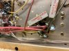
Here are the original connections to the C1D that was part of the original 4-part filter can when I first got the unit. The green/yellow wire and the yellow wire coming off tab 3 of the center channel output tube (same wires we’ve been talking about) both connected to the positive tab on the C1D, which was then, of course, grounded by the can. If I hook up my new C1D cap across off the big resistor coming off tab 3 of the center output tube, I’m just not following how to connect these two wires to complete the circuit properly?

AEF44F92-684E-4288-B325-7A062A4A9A29.jpeg
 
is the yellow wire the one coming from pin 3 of the center channel output tubes? if so, just connect it to the green/yellow wire coming from the power transformer.
 
Gadget - Yes, you are correct! That is what I was thinking, but wanted to be sure. I'll connect those two, and for the C1D cap, I will attach the positive lead to the side of the resistor connected to pin 3 and the negative lead to the side of the resistor that is grounded. Sound right to you?
 
Thanks, Gadget. It will make for a neater wiring situation, too. This thing is a bit of a rats nest.
 
Well, after relocating the C1D cap across the resistor on the center output tube, replacing the three out-of-spec ceramic disc caps in the amp and a majority of the out-of-tolerance ceramic disc caps in the pre-amp (2 were just too hard to get to), the hum unfortunately remains. Rechecked all the soldering connections and wires in the amp and the pre-amp, and everything appears good. Didn’t touch any of the resistors, since none are reading high. Pulling the center channel 12AX7 still quiets things down — so the root problem remains.

Pulling the single 12AX7 in the pre-amp doesn’t stop the hum either, so I assume that points back to something in the amp being the problem. But, darned if I can find it in spite of all the great help provided here. Tried hooking the power cord up to an extension cord connected to an outlet on another circuit, no dice either. So, I prudently walked away and cracked open a beer.

The tech working on my Sencore Gm tube tester was able to fix it, so I should be able to test the output tubes soon. But, given that the tubes are new and were purchased as a match quad, I don’t think this is going to be a tube issue either. May need to find a Tech I can ship the amp off to to explore this further. Wish I had better news to report. Thanks to all who have offered me assistance.
 
Last edited:
Back
Top Bottom