

You are using an out of date browser. It may not display this or other websites correctly.
You should upgrade or use an alternative browser.
You should upgrade or use an alternative browser.
I've got a Bogen "Challenge"
- Thread starter RUmad
- Start date

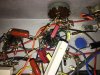


Hey man, that is work too RUmad!
I have a couple of questions for you...
Is the amp fairly quiet, meaning not much hiss at volume?
Did you clean the selector switch with some Deoxit?
Do you primarily plan to ditch this as a guitar amp, and make/keep the tone stack hi-fi frequencies?
I have a couple of questions for you...
Is the amp fairly quiet, meaning not much hiss at volume?
Did you clean the selector switch with some Deoxit?
Do you primarily plan to ditch this as a guitar amp, and make/keep the tone stack hi-fi frequencies?
Last edited:

RUmad
Super Member
Thank you sir. This amp is dead quiet. No hum, no hiss, and I use it with a 100 spl speaker. I do plan on ditching the guitar input in favor of running audio through both pre tubes. So, I'll lose one of the input volume pots, lose the tone selector, and would like to add treble and bass tone pots between preamp tubes.
I figured it would be dead quiet. Mine was too. Very loud, no hiss at all.
I also believe that Your select-o-tone circuit is still all contained within the Neg. Feedback Loop.
The OT pin 6 (orange wire) leaves the transformer and goes to the tag board under the 4-way switch. It is tied to two 100K and a .003uf that all go to positions 2, 3, and 4. There is also a (Red) 500pf that goes between the plate of a 6v6 (pin 3) and position 2 of the switch. There is a 47k between position 1 and 4. The Common of the switch connects through a 47k to pin6 of a 6v6 socket (unused, tie point) and the white wire travels over to the 6SL7 and enters at pin 3.
My goal differed from yours, so my tone circuit is completely wrong for you, or I would gladly share.
I think Repair_guy is right, you could take the tone control circuit from the schematic he shared, and graft it in.
It's hard to tell from the pictures exactly what you have going on in the RCA / phono / Guitar input area, but if you have nothing tied to the Red wire that is between the original phono input and the phono volume control, you can safely remove the 470k that is between pin 3 on the 2nd preamp tube and the phono volume. (leave the other 470k from pin3 to gnd) Then use that control for one of the tone controls.
When I removed my select-o-tone circuit, I could hear some noise. so you may have to do some research on how much neg. feedback you need to help quiet it back down.
I also believe that Your select-o-tone circuit is still all contained within the Neg. Feedback Loop.
The OT pin 6 (orange wire) leaves the transformer and goes to the tag board under the 4-way switch. It is tied to two 100K and a .003uf that all go to positions 2, 3, and 4. There is also a (Red) 500pf that goes between the plate of a 6v6 (pin 3) and position 2 of the switch. There is a 47k between position 1 and 4. The Common of the switch connects through a 47k to pin6 of a 6v6 socket (unused, tie point) and the white wire travels over to the 6SL7 and enters at pin 3.
My goal differed from yours, so my tone circuit is completely wrong for you, or I would gladly share.
I think Repair_guy is right, you could take the tone control circuit from the schematic he shared, and graft it in.
It's hard to tell from the pictures exactly what you have going on in the RCA / phono / Guitar input area, but if you have nothing tied to the Red wire that is between the original phono input and the phono volume control, you can safely remove the 470k that is between pin 3 on the 2nd preamp tube and the phono volume. (leave the other 470k from pin3 to gnd) Then use that control for one of the tone controls.
When I removed my select-o-tone circuit, I could hear some noise. so you may have to do some research on how much neg. feedback you need to help quiet it back down.
RUmad
Super Member
Clearly you know your $hit more than I do. Maybe that's why I was confused, looking at the schematic and seeing the actual circuit I would've thought the tone was after the phase splitter. Which didn't really make sense to me to begin with, as passive tone controls attenuate the signal, so it'd need more gain after being filtered. That's what ice read anyway. Most of the equipment I've worked on/built has been either replacing parts or building from scratch. What's going on at the inputs; mic input is now guitar input. Goes straight to preamp tube 1, as is always did. I added a 68k resistor in series, also added a 1.5k cathode resistor with a 25/50 bypass cap a la fender tweed.
Mono rca jack, as originally, goes through the volume pot, straight to preamp tube 2. The stereo inputs (on the left side chassis) are blended and go to the same pot as the mono jack. It worked out great, so I can hook up a mono source or a stereo source and it sounds wonderful. Although, because it isn't switched, I could technically play both (stereo and mono) at the same time. I'll have to do some more research on the schematic he provided, I'm sure you're right, I just don't want to start 'trying' things out and ruin a good thing.
Thanks for the help brother, much appreciated.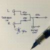
Blend circuit
Mono rca jack, as originally, goes through the volume pot, straight to preamp tube 2. The stereo inputs (on the left side chassis) are blended and go to the same pot as the mono jack. It worked out great, so I can hook up a mono source or a stereo source and it sounds wonderful. Although, because it isn't switched, I could technically play both (stereo and mono) at the same time. I'll have to do some more research on the schematic he provided, I'm sure you're right, I just don't want to start 'trying' things out and ruin a good thing.
Thanks for the help brother, much appreciated.
Blend circuit
Last edited:
RUmad
Super Member
What about a temporary way to remove it from the circuit, see how it sounds? When I desoldered the resistor that feeds the switch, changing positions didn't effect tone. Was it effectively removed at that point? Or would I have to disconnect ALL of the components? Like I said, I'm hesitant to make too many moves and mess it up.
Thanks for the kind words sir. I don't know all there is to know, and I am trying to learn more. I have stared at the schematics, and the amp, and asked questions.
Pulling the 47K that goes to pin 6 on the 6v6 should effectively remove the tone control, but it also removes all negative feedback.
You can also just remove the orange wire from the OT, and/or the white wire from pin 3 of the 6SL7.
That is just two connections, and easily returned back to stock.
My experience was that removal introduced some noise or hiss. I believe it was due to also removing the "anti-noise" that is being fed back and cancelled out at the PI.
I did a search for "effect of negative feedback on frequency response" and found some useful information... including this link
http://www.learnabout-electronics.org/Amplifiers/amplifiers30.php
The LE circuit you posted uses a dual 4 position switch, to create the tone stack.
What about a temporary way to remove it from the circuit, see how it sounds? When I desoldered the resistor that feeds the switch, changing positions didn't effect tone. Was it effectively removed at that point? Or would I have to disconnect ALL of the components? Like I said, I'm hesitant to make too many moves and mess it up.
Pulling the 47K that goes to pin 6 on the 6v6 should effectively remove the tone control, but it also removes all negative feedback.
You can also just remove the orange wire from the OT, and/or the white wire from pin 3 of the 6SL7.
That is just two connections, and easily returned back to stock.
My experience was that removal introduced some noise or hiss. I believe it was due to also removing the "anti-noise" that is being fed back and cancelled out at the PI.
I did a search for "effect of negative feedback on frequency response" and found some useful information... including this link
http://www.learnabout-electronics.org/Amplifiers/amplifiers30.php
The LE circuit you posted uses a dual 4 position switch, to create the tone stack.
RUmad
Super Member
Ok, thanks brother. I'll check that info and, after I finish my Fisher restorations, I'll get back to that Bogen and see if I can't figure it out. appreciate help.
Yeah, I did remove that resistor, and I don't remember if it induced 'noise', but I do remember it's isn't sound 'right'. Sounded thin I think. I'll try it again soon, maybe add just a 22k resistor NFB, see how that sounds.
Alan
Yeah, I did remove that resistor, and I don't remember if it induced 'noise', but I do remember it's isn't sound 'right'. Sounded thin I think. I'll try it again soon, maybe add just a 22k resistor NFB, see how that sounds.
Alan
RUmad
Super Member
Hey Duce, not trying to annoy the hell out of you. One more question. After looking at your schematic, which all of a sudden I'm liking more than mine, I'm thinking if I disconnect the 47k from the switch, run a jumper from #6 terminal (orange wire); there's my unmolested feedback loop no? At least a good place to start. Doesn't solve adding the first preamp tube but that shouldn't be so difficult. If that works I may not even need tone adjustments. I've never used them in my scratch builds anyway. Sound right?

RUmad
Super Member
That's exactly what I was thinking. I think we got it figured out man. Totally appreciate the heads up on that NFB! Would've taken me forever to find it, not being on the schematic I had. Now to test that theory and find a simple way to run the audio through both tubes and maybe not even need tone. THANK YOU!
RUmad
Super Member
Ok the good news the bypass worked great. That terminal strip is in a heck of a spot, so I removed the orange wire at the opt, disconnected the 47k from the switch, and jumped from the tranny to the resistor. No hiss, decent sound. Seems to have lost gain and treble needs attenuating, so at least it worked. I'll have to put it on the back burner for a bit but I think, maybe, playing with resistor values I the NFB and, back to the original plan, adding in that first tube with controls in between is the way to go. I think it's less complicated than I'm making it to be. To be continued.
For now I'll put it back to original and listen as is.
For now I'll put it back to original and listen as is.
Attachments


I'd just go with a basic resistor as the feedback, ditching the controls and all that nonsense. Try just a 150k from the 70v terminal straight into pin 3 of the 6SL7, with all of the other stuff unhooked. That should give you some feedback to knock the gain back, but without any sort of contouring or anything like that.
RUmad
Super Member
Yes, that was going to be part of the plan after I got the first tube incorporated into the audio circuit, ditching the guitar (mic) input entirely. Or are you saying that more NFB would lower the gain enough that I should just couple the first to the second, at existing bias, and I may be able to work like that?