• The move to the new server is done. There are some software and database maintenance updates in process. This has us passing the hat around to help out. We appreciate any donations. Seriously, even a dollar helps. The payment page may be found here - https://www.audiokarma.org/support.html

JBL 4435 Recap and Mods with a Little Help from the Easter Bunny

FireGuruMN

Active Member
I have another thread in the "Lansing Legacy" about these speakers also:
https://audiokarma.org/forums/index.php?threads/jbl-4435-bucket-list-countdown.901225/
That thread talks about positioning and replacing the diaphragms in the horns. The executive summary:
Position them wherever they will fit.
Replace the factory diaphragms with Radians.

I've been on a kick to replace capacitors in all my speakers. I was having an internal debate about whether these 4435's needed new caps or not. Since you are reading this I obviously decided they do need replacing. What drove me over the edge was that the speakers did not sound the same. I cleaned, positioned, polished, adjusted and measured everything I could with the exception of the components on the crossover.

Seems like COVID is starting to limit supplies of some things like Solen capacitors (France) and Mills resistors (Mexico I think). So after waiting for backorders and other delays I eventually acquired everything I need:
(quantity per speaker)
Resistors (you really do not need to replace resistors in most cases. All my removed ones were just fine It's a guy thing:
Qty 4 of 62 ohm resistors. 71-RS10-62 (mouser). Kind of nice because they are the same size as the originals. Bigger than Mills, black, cheaper. Hard to find 62 ohm values.
Qty 1 of 5 ohm resistor. Original was 5.1. 71-RS0105R000FE73 (mouser)
Qty 1 of 10 ohm resistor. 71-MRA-1210R00FE12 (mouser)
Qty 1 of 20 ohm resistor. 71-MRA-1220R00FE12 (mouser)
Capacitors:
Qty 2 of 15uf capacitor. I like Solens. Live your own life. 027-576 Solen 15uF 400V Polypropylene Capacitor (parts express)
Qty 1 of 12uf capacitor. 027-572 Solen 12uF 400V Polypropylene Capacitor (parts express)
Qty 1 of 2.2uf capacitor. Original was 2.5 but that is not a common value or they were out of stock. With a 0.15 bypass it is close enough. 027-558 Solen 2.2uF 400V Polypropylene Capacitor
Note: There is also a 20uf capacitor with a bypass that is only in the circuit when you switch to an external crossover. I modified my speakers (read on) so that capacitor was never in the circuit. I think it was mostly just a safety in case someone tried to run full power low frequencies through the horns. 20uf is not a sensible value to have at that position in the circuit when it comes to crossover frequencies..

Bypass Capacitors. Get whatever kind you want. It's a personal thing. Originals are all 0.01uf. I got 0.10 and 0.15 for my own reasons and what I had laying around. It really is a tiny value compared to the main capacitor. Blue on Black, Smoke on Fire, Whisper on a Scream (Great song). If you have super nice main capacitors do you even need bypasses. I'm not getting into that here.
Qty 1 of 027-127 Audyn Cap Plus 0.15uF 1200V Double Layer MKP Metalized Polypropylene Foil Crossover Capacitor (I used this on the tweeter, I ordered it for LPM100's until I realized how huge it was. Always check dimensions on caps)
Qty 2 of 027-710 Audiocap PPT Theta 0.10uF 600V Film/Foil Capacitor.

Inductors are just fine how they are. If you want to get air core or something else to prove your manliness go ahead but you will probably need to build a separate board or something to mount them.

Binding Posts. Whatever you want. Or just leave the originals in place. I just used two posts per speaker but if you ever want to bi-amp them you will need 4 posts.

There is some Easter Bunny connection further on. But it's mostly just to make the post title more interesting than just another 4435 recap. Really, if that was not in the title would have gotten this far?

Continued. . .
 
Last edited:
Register to hide this ad
Fortunately you can service the entire crossover from the front. Pull out the 15" driver on the side with the level adjustments (opposite the horn).

The crossover is probably covered with some insulation on the back of the speaker where the speaker terminals are. It is held on with six threaded bolts. Be careful, the crossover has some hefty inductors on it so it is a bit heavy and lopsided. Take lots of pictures. There are 19 (or so) wires connecting to the crossover. There are references online for where each and every color goes but just label them. And try to label them accurately. I messed up a bit.
The wires from the amplifier come right along with the crossover. It's a major production to get to mine otherwise:
upload_2020-5-1_19-35-42.png
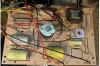
Side view:
upload_2020-5-1_19-33-27.png
other side:
upload_2020-5-1_19-33-55.png
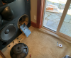
It was a beautiful day and my wife complained that I should get outside. So I opened the patio door. . .
upload_2020-5-1_19-36-42.png
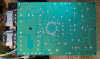
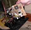
The back of the crossover:
upload_2020-5-1_19-37-49.png
Cut the two tie wraps by the inductors (already gone in this picture). Remove 6 silver screws and 4 black screws. Then remove the nut on the switch other side by the speaker terminals so you can open it up.
Lots and lots of wires. Some are short and really try not to put any tension on them.
upload_2020-5-1_19-40-41.png
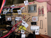
This is the after picture (spoiler alert) but label each and every wire as you take it off:
upload_2020-5-1_19-43-24.png
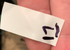
I never ever found a terminal 17. I don't think there is one. Probably an interesting story there but whatever. Be very sure to put lines under your numbers so you don't get 6 and 9 mixed up.

Continued. . .
 
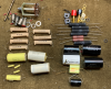
Here is everything I took out and everything I put in:
upload_2020-5-1_19-46-33.png
As you can see at the top, I removed the external crossover switch. More details on that later.
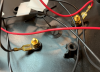
The binding posts were joined on a common plastic block. I cut the block in half and made them mostly circular on a bench grinder. I ALWAYS put in that plastic piece. With out it the posts do not seem to sit correctly. You will have to drill out the plastic plate for the new posts to fit. The size of the hole depends on your posts. There are spade lugs on the existing terminals. I drilled these out also and screwed them in.
upload_2020-5-1_19-49-41.png
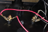
If you bi-amp then you will do all 4 holes like this. If you are not sophisticated enough (or crazy enough) to bi-amp then do what I did and put all the inputs on the same terminals:
upload_2020-5-1_19-53-14.png
If I had it to do over (and if I had enough jacks in house) I would have installed all 4 jacks and run external jumpers between them. But that makes for more drilling and more connections but it would be cooler. Maybe in the fall.
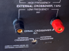
The visible side:
upload_2020-5-1_19-56-12.png
Next step for me: Remove the internal/external crossover switch. Note: This IS NOT a bi-amp/normal switch. It has nothing to do with that. JBL sold an external crossover that could be rack mounted. I'm not sure of all the details or how that even makes any sense. Feel free to google it. Since I don't have/want/need an external crossover and the external crossover switch oxidizes and causes the speakers to fail it has to go. There is a writeup of how to remove it on 4430 speakers here:
https://audiokarma.org/forums/index.php?threads/cheap-and-pretty-easy-jbl-4430-upgrade.537606/
The process is pretty much or even exactly the same for the 4435's because I did not realize it was for 4430's until I tried use his schematic to see what capacitor values I needed for the midrange. There is no midrange on a 4430. . .
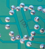
So suck all the solder off the terminals:
upload_2020-5-1_20-3-11.png
Some of the leads are bent over so straighten them up. Then apply some angular pressure to the switch and heat up the left over solder and after a bit the switch will free up. Be careful with the brute force. This is not a military spec circuit board.
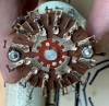
Looks like something from the Matrix when you remove it:
upload_2020-5-1_20-5-40.png
You can see the corrosion that prevents good contact on the switch. And how impossible it is to get deoxit under the switch. That corrosion is your music turning into heat.
You are left with this on the circuit board.
upload_2020-5-1_20-7-24.png

Continued. . .
 
Install jumpers to get this configuration:
upload_2020-5-1_20-8-50.png
The crappy looking label says "E3" with an arrow. One step I missed on the original instructions was to relocate the "E3" wire connector to this location on the PCB. Maybe it just me but I still don't see that step except in a schematic picture.
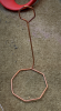
So where to get the wire to make the jumpers?
upload_2020-5-1_20-11-21.png
Recognize this? That's the Easter Bunny tie-in. It came with the egg dying kit. Yes, I know, most people would just use some of the leads cut off of the capacitors as you install them but I was not thinking clearly and I knew where this was. Yes, it is solid copper, not copper plated aluminum.
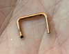
Make some jumpers of the appropriate sizes:
upload_2020-5-1_20-14-3.png
Soldered and trimmed:
upload_2020-5-1_20-14-50.png

Next do the resistors or really whatever you want to do next.
upload_2020-5-1_20-16-40.png
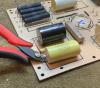
Notice that the resistors have built in standoffs to keep them off the PCB. Cool. I have not see that before (newbie). Make sure you standoff the new ones a bit. I left the glue in place to act as a standoff.
The capacitors are glued down pretty well. It might be hot glue but it is really good hot glue. Maybe you could melt it a bit but "ain't nobody got time for that":
upload_2020-5-1_20-19-3.png
I cut the glue with a nippers and it actually pries it up at the same time. There are nasty cracking noises as I did this but it was just plastic peeling off the capacitors, not the PCB breaking. Yes, unsolder the capacitors first.
Eventually all the caps and resistors get replaced:
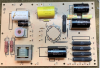
upload_2020-5-1_20-21-53.png
I think I used too much hot glue if it is actually possible to use too much hot glue.
The big white capacitor at the top left is the BYPASS cap and the small one is the main cap. Nuts.
The yellow 20uf and bypass at the top never get into the circuit once the switch is removed.

If I did it again I would get all black resistors. I like the look with the black capacitors. Even though I will hopefully never see this board again.

Continued. . .
 
The other switch was not as corroded. Wonder why.
upload_2020-5-1_20-26-10.png
But check out the green corrosion on the galvanized metal:
upload_2020-5-1_20-27-10.png
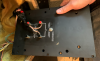
There are 1000 better ways to cover these holes than putting bolts and washers into them. But do cover the holes or every spider in your house will get in there.
upload_2020-5-1_20-29-39.png
I found mouse droppings and seeds in one of mine. They must have had the covers off at one point and they went into the vent ports.
CAREFULLY reconnect all of the wires. RETENSION the connectors as you put them on. Several of mine were loose enough to matter.
upload_2020-5-1_20-30-59.png
When all the drivers are connected I ended up with something like a 3.3 ohm reading with a digital multi meter. Don't expect 8 ohms. Resistance is different than inductance. Google it. I measured the other (untouched) speaker and it had a similar value. When I did the second speaker, I ended up reading a 1.5 ohm resistance. Something was wrong. Somehow I had two wires numbered "16". I will never know what brain cell miss fired to cause that to happen. I ended up going back and looking at my pictured to resolve the issue. Nothing blew up but one of the 15" drivers had no sound when I had it hooked up wrong. I really should have never hooked it up after getting the bad resistance reading but no harm done in this case. I hooked mine up to ensure all drivers were working before screwing everything back together. Be sure to replace the tie wraps so there is no tension on the connectors. I was half tempted to solder all the connections but I did not at this time. Be sure to put the 4 metal cylinders back in place before screwing the crossover back together. It is a pain to get the middle one in if you forget it and put the silver screws in first. Plug your amplifier wires back in and screw the crossover to the back of the speaker again. When installing the driver be sure to twist the green wires so they cannot get in contact with the driver. It should have been like that when you opened it up.

Continued. . .
 
So, how do they sound?
The vocals/midrange is much much richer and clear. That seems to be a pattern with all the capacitor replacements I have done. The original speakers were super bright with the original diaphragms. That got much better with the Radians. Now the brightness is entirely gone but I think it might have gone all the way to "dull". I have not measured anything with instruments so this is all subjective. Maybe I just liked the bright sound before with my fading hearing? It did make for a very pronounced sound stage. These speakers have always had fabulous bass and that has not changed. Maybe it has gotten better/smoother? The speakers sound more balanced with the new components and switch removal. They were almost comical when I first heard them with super bright horns and thundering bass but not enough in between. That problem is entirely gone now. Balance. A good thing.

I'm going to let the new capacitors and such burn in for a while and get back to you with a final opinion. I'm working on hooking up a remote control speaker switch so I can do some proper comparisons. I might even take some objective measurements with some geek equipment. Maybe.

Stay safe.

And if anyone has a use for this, it's all yours:
upload_2020-5-1_20-50-10.png
 
EXCELLENT Work ! And thanks for documenting so well for posterity!
Almost (but not quite) makes me want to crack open my 40yr old N8000s:)
Curious: did you consider taking REW measurements before/after? :)
 
Fire,I'll be curious to see how measuring or a/b-ing with an original diaphragm turns out. I have two pairs of 4435's,in stock form. I have never been thrilled with the treble. Fiddled all kinds of ways with the l-pads,eqing,inner & outer positioning and toe. I know part of my issue is reflection and they're in a vaulted ceiling room. I just wish they were a bit more dynamic. When I crank them up they go somewhere between dull and shrill. I hope to move them into a more suited room,and treat appropriately,in the meantime,great work on both threads,I'll be following. Also,turning the horns and cabinets is tougher than just flipping the horns. There is bracing that supports the horn driver,and you'd also have to alter the cabinet to have the proper mounting keeps that the horn bolts into. That's just off the top of my head,I thought about trying a pair vertically some time back. I also have a non mirror set of 4430's I'd like to mirror one day but I can't see butchering a cabinet to do it. Thanks again for the wonderful threads!!!
 
Quality write up.
Normally I'd have skimmed and got board,
Pictures at the right time.
Well done. And nice work.
I use hot glue too. And good stuff. Caution on the resistors. Or you could make sticky traps for the spiders.
 
When I crank them up they go somewhere between dull and shrill.
When I heard these at the previous owners basement I almost was ready to pass on them because they sounded like they could peel paint off and air craft carrier. Then I noticed what he was driving them with:
  • An old Yamaha receiver with base and treble maxed out and loudness on.
  • Some sort of QSC amp.
  • An ancient DBX equalizer with an EQ curve that would put the Swiss Alps to shame
I managed to bypass the EQ and set the receiver controls to flat and something resembling music could be heard. So I took a chance and paid the man.
  • The first big improvement was cleaning the internal/external crossover switch. I cleaned the midrange and treble controls also but that did not have much effect other than making me feel like I did a complete job.
  • The biggest improvement was putting in the Radian diaphragms. I highly recommend that step.
  • Lastly I replaced the crossover caps and resistors. I'm not sure I would do that again if I had a choice. That step definitely fixed the problem with one of the speakers lacking midrange. So now they are well balanced but they lost something in the recap. I don't know how to put it into words but acoustic guitar and saxophone sounded ridiculously vivid before I recapped them. And that is gone now. I want it back. But I suspect it is gone like my youth and other less tangible things. Some would say that the Solen caps that I used for replacements "just sound like that". Mellow. Smooth. And I lean toward sharp. Again, using words to describe sounds is like describing color to a blind man.
I have not experimented much with positioning them nor with room treatments. There is little I can do in my room to choose different positions. And if I found something that sounded great I would have to put them back against the wall in the end or "quality control" would get rid of them.

I still love the sound of these speakers. And interestingly the family dog is either afraid of them or also enjoys them. I am not sure. When I sit down for a listening session with wifey out of the house the dog will usually come down to sit with me. I suspect that the booming bass sounds enough like thunder/fireworks that the dog is scared and wants me to keep her safe. When I switch to other speakers she will not come down even if I add subwoofers. But these JBL's probably have the best low end of anything I own (so far).
 
  • The biggest improvement was putting in the Radian diaphragms. I highly recommend that step.
  • I don't know how to put it into words but acoustic guitar and saxophone sounded ridiculously vivid before I recapped them. And that is gone now. I want it back.
Are you sure that it was from the recap and not the Radians? Granted the Radians may be smoother at the top end (I also had a problem with the titanium brightness), but maybe they lose it through the mids and these speakers need all the mids they can get.

If you do think it could be the caps, I found that Aerovox caps have a bright/there sound you may prefer. It is certainly brighter than the ClarityCaps.
 
A while back I bought a calibrated mic and I finally got around to running some tests on my speaker hoard. Starting with my favorites.
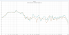
My goal in this experiment was to get the flattest response possible out of the 4435's by playing with the built-in Lpads. Curiously this is what I found out:
upload_2022-5-15_20-10-39.png
My flattest response was with the mid pad set to minimum and the high pad set to maximum. At least that is what happened in my world. Your results may vary.
I ran a whole bunch of tests to determine the amount of variability that was possible with the Lpads. But all those readings have disappeared from my world. I've got 20 terabytes of NAS and they could be hiding anywhere. When I find them I might continue this conversation. Or maybe its easier to just run new ones. But there is just so many times you can listen to a 20-20 sweep before the neighborhood dogs starts howling. And the howling messes up the readings.
Since I'm a bit of a purist, I put the pads back to "zero" for normal listening. I cannot say "center" because the pads have more adjustment on one side than the other.
Regardless, the best part of these speakers is that huge hump between 20hz and 200hz that rattles your fillings. I've never met a speaker that matched it.
 
The L300 is not that different. It has a better top end, but doesn't soundstage/image as well. I had both the 4430s and L200/300s and would run them side by side. The 4430s use the mass rings so have even more depression in the midrange (the classic JBL "veil"). This is why I created the Mermans.

index.php
 
The 4430s use the mass rings so have even more depression in the midrange (the classic JBL "veil").

With the 4430's I just got, While I have my Woofers out for a pro Refoam,
I'm going to try out several different JBL's I have to help get rid of the Veil,
and increase their overall efficiency
1st ones will be the D140-F's with the Large cloth surrounds.
BTW I did try adjusting the l-pads as per FireGuruMN's recommendation, and they did improve.
Love those Butt cheeks horns
 
Back
Top Bottom