• The move to the new server is done. There are some software and database maintenance updates in process. This has us passing the hat around to help out. We appreciate any donations. Seriously, even a dollar helps. The payment page may be found here - https://www.audiokarma.org/support.html

JBL C40 Harkness N1200 Crossover Recapping

cykotic

New Member
Greetings:
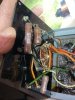
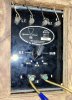
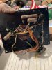
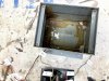
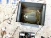
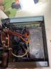
I have an early model JBL C40 Harkess with the D130A, 175DLH, and N1200 Crossover. I would like to change the capacitors in the N1200 as they have to be about 60 years old now (or older). I opened up the N1200 and am faced with this wax/resin substance securing the caps to the inside of the metal enclosure. What is the best way to go about removing the resin to free the existing caps? Or can I bypass the removal some way and just rewire new caps into the enclosure? Any advice would be appreciated.
Thanks much,
~Cykotic
JBL N1200-1.jpg JBL N1200-2.jpg JBL N1200-3.jpg
 
Register to hide this ad
Do you have a schematic for the N1200? If so try to follow which posts they go to and cut the wires long. Then you can solder them up to your new caps. Make sure you identify the cap values you cut. I think there is only 3 or 4 caps in that crossover. I have and use a hot plate to melt that ****. If doing so you must keep a close eye not to bring it to flash point. Also have some oven gloves and a pie plate to pour out into. I only reuse the beeswax/resin for replacing the inductors in larger 3 and 4 way ones. Once it is melted in the box you can lift the whole assembly out. On the corners of the JBL crossover boxes you will have to put some duct tape to stop the goo from leaking out onto the hot plate. If they are not totally sealed. You might be able to just set your new caps in without doing this process. Then put a lite fill of insulation in to keep stuff from moving around.
 
Yes. I have the schematic for this N1200. Thanks so much for the advice. I will pick up a hot plate and melt that resin out of the box as everything is sealed to the bottom of it. I want to make sure I wire it properly. Thanks again! :-)
 
You do not have to pour it all out then. Get it melted and just lift it all out. Make sure your surface is non stick like a glazed plate
 
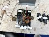
JBL 1957 C40 HARKNESS LOWBOY N1200 CROSSOVER-4.jpg JBL 1957 C40 HARKENESS LOWBOY N1200 CROSSOVER-3.jpg JBL 1967 C40 HARKENESS LOWBOY N1200 CROSSOVER-2.jpg JBL repalcement Daytom Capacitors.jpg JBL 1957 C40 HARKNESS LOWBOY N1200 CROSSOVER -1.jpg

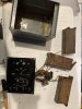
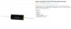
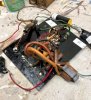
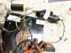
I finally got around to melting that wax resin out of the early JBL N1200 crossover and ordering new capacitors. I am very new to this type of audio upgrade. As such, I need some advice. I am on PartsExpress.com and am about ready to order these Dayton Polypropylene capacitors as replacements. Are these capacitors the route I wish to take, or should I choose a different brand and composite? Thanks.

PS: XYLENE is the solvent that will cut through that weird wax/resin which holds the components in place within the early (1962) JBL N1200 crossovers with the gray metal case,
 
Last edited:
Yes those will work good. I have used in some rebuilds Solen fast caps and would bypass with Theta .01uf film and foil caps. There are lots of different caps available and some can cost quite a lot. If you going to sell when done just go the average route and it will still be better than stock. Check out this site on higher grade caps.
Partsconnexion
 
I would also change your input binding posts while you are making changes.
Thanks much. I am renovating this crossover to perform better with my vintage Sansui 5000A. I plan on keeping this JBL C40 as the 130A and 175DLH are pristine. This N1200 had never been serviced and who knows what year it was built. It's the gray heavy metal box with the components sealed with a wax]resin I had to melt out.
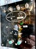
After trying several solvents, I determined that XYLENE is the reducer that will clean the remaining wax/resin off of everything. I am actually in my workshop now and have combined the new Polypropylene caps in parallel to match the 13.5 microfarad cap, and the one 16.5 microfarad cap. Figuring out the rest of the wiring right now and should have this early N1200 back together sometime after dinner Or maybe I just wait until tomorrow. By the way, while i have you, the serial number of this JBL Signature Sound N1200 16ohm is 2931. How can I determine from that serial number the date that crossover was manufactured?
Thanks much! :)
 

Attachments

  • JBL N1200 CROSSOVER - SERIAL NUMBER  2901.jpg
    JBL N1200 CROSSOVER - SERIAL NUMBER 2901.jpg
    141 KB · Views: 45
  • JBL N1200 CROSSOVER LABELED.jpg
    JBL N1200 CROSSOVER LABELED.jpg
    179.1 KB · Views: 48
  • JBL EARLY N1200 GRAY STEEL CASE FOR CROSSOVER.jpg
    JBL EARLY N1200 GRAY STEEL CASE FOR CROSSOVER.jpg
    150 KB · Views: 39
  • JBL N1200 CROSSOVER - NEW CAPACITORS.jpg
    JBL N1200 CROSSOVER - NEW CAPACITORS.jpg
    150 KB · Views: 41
Last edited:
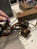
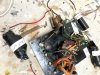
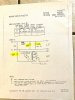
Well, I have the new capacitors hooked up (I hope correctly). I plan on using additional black electrical tape to cover the soldered joints. I have the 16,5 mf cap installed on the + red wire to the - red wire. The 12 mf cap is connected to a white or (dirty beige) + wire, then to a white or (dirty beige) - wire which ends at the existing resistor soldered to the board. The 13.5 mf cap is attached to a greenish-blue + wire and a greenish-blue - wire. I followed the attached schematic diagram and it looks correct to me. Although I could be wrong. I was planning on using some fiberglass insulation to secure these new parts into the case and away from the possibility of touching each other over a period of time either from moving the C40 cabinet or switching the Gain from low to high all the time. Is fiberglass insulation what is recommended since we no longer have access to that mystery wax/resin? Thanks for all your help with this project. My first one. I now have 2 crossovers I want to upgrade from a pair of 1977 McIntosh ML-10c's, and 2 crossovers from a pair of 1992 Cerwin-Vega Dx9's
 

Attachments

  • JBL N1200 -3.jpg
    JBL N1200 -3.jpg
    102 KB · Views: 58
  • JBL N1200 - 1.jpg
    JBL N1200 - 1.jpg
    155.5 KB · Views: 49
  • JBL N1200 -2.jpg
    JBL N1200 -2.jpg
    129.6 KB · Views: 54
  • JBL N1200 SCHEMATICS.jpg
    JBL N1200 SCHEMATICS.jpg
    75.5 KB · Views: 60
Hello Cykotic, the JBL N1200 xover started using the oval serial number tags in 1957. With your number my guess would be in 1957 or 1958. JBL used in some of their crossover models foam blocks squares or rectangular shapes to keep the components from moving around. This can be seen in JBL LX4 LX2 N7000/8000 and some others. Also to dress out your solder joints shrink warp tubing helps and can be found on parts-express site.
 
Hello Cykotic, the JBL N1200 xover started using the oval serial number tags in 1957. With your number my guess would be in 1957 or 1958. JBL used in some of their crossover models foam blocks squares or rectangular shapes to keep the components from moving around. This can be seen in JBL LX4 LX2 N7000/8000 and some others. Also to dress out your solder joints shrink warp tubing helps and can be found on parts-express site.

Great! Thanks so much! However, this C40 has the 130A in it with the black voice coil cover. I thought that the 130A wasn't introduced by JBL until 1964. Or am I mistaken?
 
JBL started the series in 1948 and it was called a D130A. In 1951 the D letter was dropped and then named 130A and the magnet structure had the flat back. In 1955 the 130A JBL changed the magnet structure to the more rounded design. Your crossover has a decal instead of the foilcal also.
 
JBL started the series in 1948 and it was called a D130A. In 1951 the D letter was dropped and then named 130A and the magnet structure had the flat back. In 1955 the 130A JBL changed the magnet structure to the more rounded design. Your crossover has a decal instead of the foilcal also.

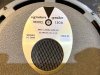
Here is the JBL 130A from my C40.

JBL 130A Serial # 12695.jpg
 
Last edited:
A little late maybe, but there's actually enough room in the N1200s for new caps on top of the potting. I did the melt thing for the first one in this thread, then just snipped the wires close to the potting for the 2nd crossover.
 
You will be far happier if you insert a 16-ohm L-pad across the output from the horn circuit and run that into the horn driver. The three settings provided by the rotary switch are far too coarse and I never found any to be just/near right. Try each one and use the L-pad to adjust the volume and see which settings of the two you like best.

You can also try adding a 1 - 1.5 mfd cap between the + input and the + on the horn driver. This will serve as a high frequency "by-pass" and put some highs into the LE175. If its too bright, a resistor can be used for attenuation.
 
Back
Top Bottom