• The move to the new server is done. There are some software and database maintenance updates in process. This has us passing the hat around to help out. We appreciate any donations. Seriously, even a dollar helps. The payment page may be found here - https://www.audiokarma.org/support.html

JBL L166 Horizons

Well, if you look at the above boards, you can see the t-nuts on the crossover board. They about 1-inch inside the top and bottom edges and maybe, 1/2-inch inside of the side edges. Now the distance to each t-nut can be measured by looking at the t-screws on the outside of the speakers.
Crossover screw dimesion (SMALL1).jpg

Which are 2-1/2 inch by 6-1/2 inch apart. So, I'd estimate the board is around 4-1/2 inch tall by 7-1/2 inch wide. :)
 
Last edited:
IThe one thing I noticed with them was I got a lot of woofer excursion unless I used the low filter on my receiver. Maybe it's the ported design but I don't have this problem on my other speakers.
Were you, perhaps, using a turntable as your source?
Doesn't sound like a speaker problem to me!
 
Were you, perhaps, using a turntable as your source?
Doesn't sound like a speaker problem to me!

Yes, obviously. However, I also controlled for the variables. The same turntable is in place but the speakers have changed.
 
Most everyone fails to realize that the spider is the main suspension that controls excursion. Foam surrounds don't fatigue in the same manner that cloth spiders do. Spiders stretch...Foam surrounds rot.

But, doesn't the rotting foam surround now have worse damping qualities, than a brand new surround? Kinda like worn shocks on a car, easily bouncing from a minor pothole. :idea:
 
The surround does tend to damp termination ringing, where an un-terminated / un-damped cone edge will carry a vibration traveling outward on the cone to the edge back down the cone. As the foam loses its resilience that damping ability would be lost. Also the foam's abiliy to keep the cone edge centered in the frame would diminish, which could lead to some radial movement. The foam surround serves several purposes and needs to be in good condition.

The spider is important to create the centering, and as @edgewound mentioned it controls excursion, ... not just limiting excursion but more importantly creating the correct amount of resistance and return forces. Like a well-designed suspension on a car (as you compared) the spring rate of a spider is not constant, it changes the further from the resting position it travels, and that progressive spring rate is carefully designed into the entire speaker system (much moreso than is the foam surround).
 
Last edited:
But, doesn't the rotting foam surround now have worse damping qualities, than a brand new surround? Kinda like worn shocks on a car, easily bouncing from a minor pothole. :idea:

Both suspensions serve a particular purpose. Typically you wouldn't change just one pair of shocks on a vehicle, either front or back, or left or right sides. You'd change all four. Renewed suspension on a speaker is much the same thing. Half a job is incomplete. Resuspension with both spider and surround will make a perfectly good cone/coil assembly perform as new again.
 
Both suspensions serve a particular purpose. Typically you wouldn't change just one pair of shocks on a vehicle, either front or back, or left or right sides. You'd change all four. Renewed suspension on a speaker is much the same thing. Half a job is incomplete. Resuspension with both spider and surround will make a perfectly good cone/coil assembly perform as new again.

I had my 122A re-coned. The break-in time took awhile, but the bass is now pretty nice. Even compared to the newly re-done 136A woofers. :)
 
@Mr Boochie I have gotten to listen to my speakers for the first time today. The sound is airy and clean, a little low on bass notes, actually a lot low, mids and highs are awesome. I figure that is two things, positioning and I am accustomed to a subwoofer. This with the factory crossovers, no replacements as of yet, not sure there is a reason for it yet. I was going to put up a recording but my phone evidently does not record very well. I'm pleased so far.
 
Also, the L-Pads must have a minimal effect on the sound as when I turned them they didn't change much. Does this seem right?
 
One should affect the tweeter, the other should affect the mid. It is easiest to tell with your ear next to the driver and music (or pink noise) that is playing through that driver.
 
I've got everything I need to build a brand new crossover for my L166's. I tend to overthink things a little bit. Anyways I have another question for you guys that have redone or made new crossovers for your speakers. The original crossover has the iron core inductors just completely covered in glue. Is there a good reason for this? Also, I noticed that they are placed really close to each other with the same orientation, I thought that was a no no, does the glue somehow negate the bad side effects of mounting your inductors like this, or is it that air core and iron core are different in the way they are mounted?
 
I don't think orientation of the chokes are as critical in AC circuits (like speaker crossovers), compared to DC circuits (like DC power supplies and primary lines on output transformers).

I built all my DIY crossover as 1-inch air core. I use a wooden or plastic dowel. There is less hysteresis with air-core than iron core (at least, theoretically). However, it takes more turns of wire with an air-core to yield the same inductance value.

Photo is of the 20mH air-core choke I wound for my DIY subs. :)


choke (air core, DIY) (small).jpg
 
Last edited:
Go easy on me ;) I'm not a very good solderer and this is my first time building a crossover. One side is done, now for the other. It looks right to me. Hopefully, the next one will go better and look better. What do you folks think is it going to work?
 

Attachments

  • IMG_20210325_202657399_HDR[1].jpg
    IMG_20210325_202657399_HDR[1].jpg
    91.3 KB · Views: 26
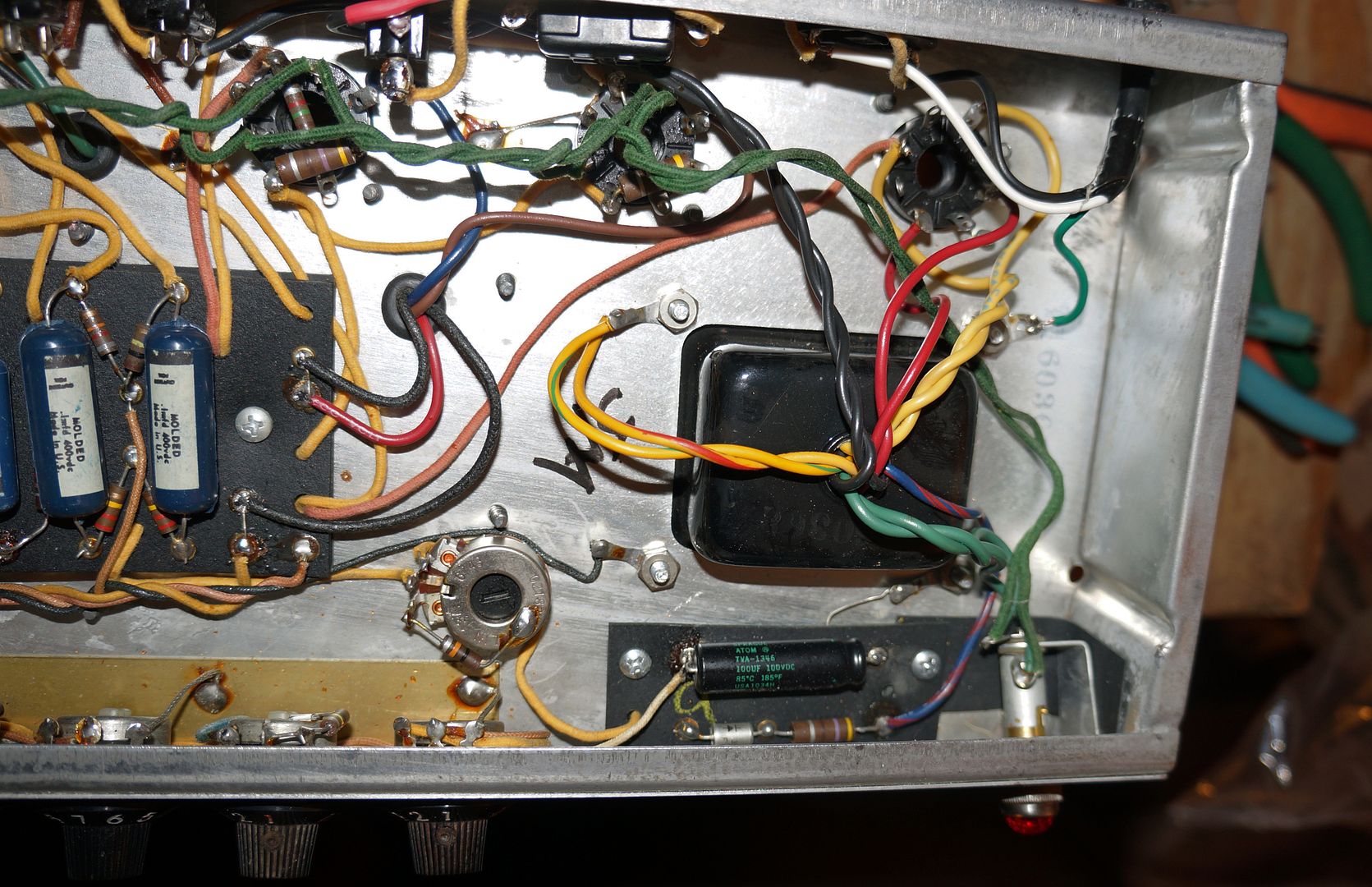
Looks fine. Make a nice, thin layer of solder over all the exposed twisted copper wiring. Especially at terminals. This will keep the leads from unraveling. Maybe, heat shrink insulation might have been a nice touch. Like what I did on the fuse holder, in photo. You can also just see the red shrink insulation on one of the power lines, above the fuse.

bias_cap_-_three_prong_cord.jpg

(Click onto image)

Test time! :thumbsup: :)
 
Last edited:
"tin" the wires first, that will help.

You hold heat on the wire until the solder wicks in. Solder will typically go toward the heat, I put the soldering tip under the wire and let the solder melt into the wire until it all turns silver. Tinning both the wire and the terminal makes it much easier for a first-time soldering job to go well and look good.
 
I knew to do that and I can not tell you why I didn't. Major brain fart I suppose. The second went a lot smoother because I did do that and because I knew how to put it all together. Now to install in the speakers and then a good listening session to see if I can hear a difference.
 

Attachments

  • IMG_20210326_162354575[1].jpg
    IMG_20210326_162354575[1].jpg
    90 KB · Views: 21
Back
Top Bottom