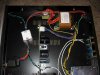
Found it!
...If you will notice the Maryland's have a little board next to the transformer. Ignore the little white box as I added that because it was sitting around.

Yes it looks like it's just a jumper. On the Shenda units they saved the labor and parts and simply terminated the wires together at the switch. Good idea, I wonder why they even had the jumper before....:scratch2:
Well, two 14.5 Hr work days down and one more to go tomorrow but I managed to get a look at the output board circuit. (Wow, disclaimer, I just had to retype that last line 4 times... I'm so tired)
The High/Low Output board was not easy to remove. It's actually soldiered on to the the RCA's after they were mounted into the chassis. I was hoping I could remove the RCA's out of the chassis to get a look at the board but I had to de-soldier them from the board to look at the back side. I'm not too upset because I wanted to reflow the soldier connections anyway.
Here's what I found!!! To my extreme surprise the caps are installed as a low signal high pass filter. This is a real head scratcher because I worked out the high pass frequency using a trim pot value of 50% and it gave me a high pass frequency of 25 Khz. (high pass frequency) HPF = 1 /(2 X 3.14 X R in ohms X C in farrads) Hmm..... High, Pass... meaning it only passes frequencies above 25 Khz????
Yes, to a certain degree. In actual practice what these caps are doing is accenting the highs above that mark. All the frequencies are equal between the high outputs and the low outputs until it reaches the HPF from there it passes more high frequencies compared to the high output signal giving the low outputs a different frequency curve compared to the high outputs.

What this means to us? Well because the HPF is dependent on the trim pot setting, it's not a consistent HPF. Furthermore, my particular JD9 had two different values of capacitance. The 4 capacitors are actually oriented in parallel two per side thus adding their values. I read 100pF in parallel with a 27pF on the left channel and 100pF in parallel with a 20pF on the Right. This difference is very minor and I doubt anyone could hear the difference between left and right on my JD9 but it still shows the quality issues that the Shenda Jolidas may have.
So, it looks like the Shenda JD9's will have a slightly brighter sound on the low outputs as compared to the high outputs. The JD9s with the capacitors removed will not have any difference in sound between the high and low output RCA from the JD9. Perhaps everyones system down the link will sound different due to the different gain coming from the JD9 but it's my opinion that the frequency response between the high outputs and low outputs of the JD9s without caps on the output boards are identical. This can be proven mathematically.
This whole circuit is very unorthodox and poses many holes by which the frequency response could be uneven between the Right and Left channels. I can post or PM if anyone wants to see a schematic.
I'll be removing my capacitors from the output board to match the Maryland units displayed here. Thanks again fellas for the participation as it's led me to find this little quirk and repair it. I'm left to wonder what the designer was thinking and I can only come up with one answer, I believe the two positions currently occupied by capacitors per channel on my JD9 was originally placed there for the option to place output loading caps to compensate for various RCA cables, perhaps another dip switch bank.... (It's a stretch) How the Shenda factory decided to put caps in there and select the values they did is beyond me. I wonder if they selected different caps on one channel to compensate for a slightly varied trim pot postion.... Just thinking out loud... I'm going to bed now.