• Please note that Audiokarma will be offline briefly for updates early on Monday morning, September 28th.

KA-7100 No Bias voltage on Right Channel

sajjad amer

Active Member
Long Story Short
Recapped, changed Bias and DC offset variable resistors. Broke Speaker Selector switch and managed to get it working , only Channel A and Channel B work, A+B do not work.
Speaker A was working fine, so I started listening to it, 2-3 notch on volume, forgot that I have not adjusted DC offset or Bias. After 20 minutes a loud thud and no sound from right channel. Fortunately speaker still works.

I have checked driver and out put transistors Q24,26, Q23, Q25 they check fine on my cheap transistor checker. I can adjust DC off set on both channels but Bias on left channel only. Bias voltage on Right CP is 0.

Could some one please guide me in the right direction?
 
Register to hide this ad
On further testing I can hear both channels working on headphones. Can someone please guide me in right direction ?
 
Did you also check the outputs themselves, Qe 27, 28, 29 & 30 ?
Just wondering if you're hearing the audio (on headphones) via the drivers, but have one or more outputs failed.
 
I pulled them out and checked with transistor checker.
I have replaced 2sc915 with 3503 although they checked fine as per advice from experts on this forum. But rest are the original transistors. If I take the voltages across the transistors in circuit would you please interpret them for me? I cannot figure it out myself.
Many Thanks
 
I can certainly try - but I would suggest you only power it on via DBT for the time being, to minimise any potential for further damage.
You should be able to get an idea of where the problem is by comparing the voltages between the good & bad channels.

OK, just found your earlier thread - I'll have a read through it.
 
Last edited:
Would have been a bit easier if you'd kept to the same thread - it's simpler for others to follow.

I'm not convinced you've got the right speaker select switch, did you ever finish confirming the continuity for the various speaker switch positions / wiring ?
If not, I'd probably be inclined to follow some of the earlier suggestions, or eventually just bypass (completely disconnect) the speaker select switch for now, until you have the amp working properly at least. The switch is just an unnecessary complication unless you know it's good. It should be straightforward to just wire the outputs to run via the 'A' speaker terminals for now.

Which exact transistors have been changed, ideally including Qe reference numbers (I don't follow your 2SC915 & 3503 comment).

As a side note - what was the problem with the original speaker switch, and do you still have it / the pieces ? it may well be repairable.
 
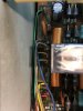
  • image.jpg image.jpg image.jpg Apologies for not being clear and providing wrong part number
  • Q-15,16,19,20 were 2sc945 replaced with KSC3503DSTU
  • I enclose wired switch picture it worked for A or B but not A+B for 20 minutes and then kaput
  • I go not have old switch I broke it while wrestling it into position, lesson learnt
  • I've traced the leads with continuity meter speaker A Right is blue+grey left is yellow black ---speaker B right is Green grey left is brown black
 
Do you have an oscilloscope? You really need one to go through the circuit and see where the signal is being lost.
 
Do you have an oscilloscope? You really need one to go through the circuit and see where the signal is being lost.
I do have oscilloscope but I'm not very confident in using it. Last time I played 100hz signal from pc and managed to trace the sine wave and cobbled the wiring to switch.
If you're would be long enough to tell me which points to check signal been I can do it.
 
What I don't understand is why I can't see any DC voltage at CP for right channel. I do not have inside knowledge of electronics but common sense would dictate that it has to be a component which drives the bias adjustment points. That's why I removed all transistors and checked them.
Have I done the correct thing by replacing above transistors ? I still have the old ones if you advise otherwise
 
You can build a simple and inexpensive signal tracer pretty easily. ("Noscilloscope") I made one - it's very handy. You can just feed a signal from a tuner or CD player (or whatever) and trace the signal through the circuit and find where it gets lost..

With the original speaker switch, a number of Kenwoods from this era wired the A + B speakers in series. Without a second pair of speakers connected it's an open circuit and you'll get no sound with just one pair connected. Not certain if the KA-7100 was wired this way but I wouldn't be surprised, and not sure how you wired the replacement switch.

 
Last edited:
I always find that type of switch very confusing to follow - but - if I'm 'reading' the switch correctly, as it is in the first picture it's connected to the 'A' speaker terminals, turn it one position, and it disconnects the 'A' terminals and connects to the 'B' terminals, turn it again in the same direction however, and it disconnects both 'A' & 'B' terminals, but connects the amp +ve outputs to ground....

I'm assuming the right & left +ve feeds from the amp are the blue wire at 11 O'clock in the first picture, and the yellow wire at 5 O'clock in the same picture.

Would be good to confirm.

Please also confirm the Qe numbers you changed again - if it really was Qe 15, 16, 19 & 20, that's a problem, those 4 shouldn't all be the same.
 

If you cannot measure bias voltage on one channel, something is wrong. You say you checked the output transistors, these really need to be removed from the heatsink to check them. Also check the emitter resistors, those big white resistors close to the outputs. Then, I would work backwards, checking driver transistors etc.

Lee.
 
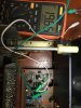
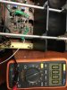
I have managed to get sound on both channels but I can hear crackling on both sides like listening to AM radio on rainy day. I can adjust bias on left but still it's zero on right side. DC offset is zero on both sides.

What should I do to diagnose the issue? Picture 1 is left channel and picture 2 is right channel. image.jpg image.jpg
 
Thank you both for guidance , I removed the out put transistors from heat sink and checked with transistor tester.
I will check thermistor and output resistors and report back.
 
all the 4 output resistors all check as 2 ohm, instead of 0.47 marked on case, I have a working trio 305 , using same resistors, they checked 2 ohm as well. Could this be the issue, but then why left channel BIAS is adjustable?
Thermister x2 check fine as well 8824ohm and 9423ohm. What is the next step
 
Back
Top Bottom