

You are using an out of date browser. It may not display this or other websites correctly.
You should upgrade or use an alternative browser.
You should upgrade or use an alternative browser.
keeping another pair of QLS1's alive
- Thread starter cdfac
- Start date

rabbit
Well-Known Member
Interesting, I thought a bit of wrinkling in the diaphram was just from long-term use and should be expected. You say wrinkling is from the EMIT being overdriven-- I wonder what the negative sonic effect of the wrinkling is? Some of my EMITs and EMIMs are slightly wrinkled; no sharp folds, just gentle waves.
My EMIT's and EMIM's are like this on my RS4.5's as well but have never been over driven. It appears that they may wrinkle because of being stretched as a result of normal usage. However I have not heard any sonic impact of the wrinkling although visually it can be quite noticeable depending on the light reflecting from them.


I had an EMIM in my RS-IIb's that was wrinkled up. It played and measured fine, but would rattle or buzz quite noticeably at certain frequencies (such as playing the heartbeat on DSOTM). I changed it out and it is now a spare.
i personally think that the rattling in emits and emims is due to fine fragments of wire or metal shavings that get trapped against the magnets and membrange. generally they would vibrate with the membrane, but at certain harmonics/amplitudes you'd expect some resonance which would be noticeable as buzzing. i pulled several such fragments out of a buzzing emit and, voila, no more problems. i sold it very shortly thereafter to an AKer, so i don't know for sure whether that was the real problem, but i never heard anything back from the buyer, and i specifically asked him to let me know since i was a little worried the buzzing would return. unless the wire racetrack is coming loose from the membrane, even a moderately wrinkled one is under such a tight grip from the magnets that IMHO the membrane has no reason to buzz.
rabbit
Well-Known Member
I had an EMIM in my RS-IIb's that was wrinkled up. It played and measured fine, but would rattle or buzz quite noticeably at certain frequencies (such as playing the heartbeat on DSOTM). I changed it out and it is now a spare.
Did you try pulling it apart and investigating whether or not that this was the cause ??
I think the later EMIMS used a kapton material and were less susceptible to wrinkling. But I have seen quite a few Betas and Gammas where the L-EMIM had quite pronounced wrinkling and the EMIM had virtually no wrinkling. I assume that the lower crossover frequency used for the EMIM's in the RSIIb's RS4.5's etc means that they have to handle lower frequencies and hence requires higher diaphragm displacement and thus stretching. Having said all of this I have also seen the later EMIT's used in the RENs also suffer from this.

I'm finally putting together a parts list for recapping. It's not going to be cheap even with Solens and the like, but the payoff should be pretty big, I hope.
I'm going to run new wire, and I'm considering replacing the resistors and inductors while I'm at it - any thoughts on this? I was planning on using 16 or 18 AWG (this original stuff doesn't look as big as the 18 AWG spec'd anyway) for all the wiring, which means I should probably use that gauge for the inductors too. It looks like all of my resistors need to be 25W, which is probably why they used 8 2.7-Ohm ones in series-parallel to get 5.4 Ohms equivalent out. Then each would only have to handle 3-4W, right? If so, I've got a good arrangement picked out that should work nicely with less soldering.
I've read about Infinity's tendency to modify the crossovers at will, and this seems to be a fine example. Instead of a 1100 uF and 1400 uF for the DVCs, the parted-out crossover I'm working from has a 1600 uF and a 1400 uF respectively. And instead of 1.25uF, 1.75uF, and 2.5uF for the tweeter XO frequency, I have 1.75uF, 2.5uF, and 3.5uF. I think that the speaker I parted out was an earlier production model since it didn't have the normal Quantum stand-off grills and it had the big MDF woofer mounting ring. I'll have to try to get a better look at my intact QLS1s to see if their crossovers are the same as these or the official specs or something else entirely. Can I get some advice from people who've done this recap themselves?
Thanks for the help.
EDIT: here's a link to two sets of schematics which I think are identical: http://infinity-classics.de/infinity/models/Quantum-series-1976/index-Quantum.htm
EDIT #2: My intact Quantums match the schematics exactly, and they sourced the exact parts to begin with (or likely the other way around). Madisound has a more appropriate selection of resistors, smaller caps, and inductors for this particular project than PE, and it's cheaper too.
I'm going to run new wire, and I'm considering replacing the resistors and inductors while I'm at it - any thoughts on this? I was planning on using 16 or 18 AWG (this original stuff doesn't look as big as the 18 AWG spec'd anyway) for all the wiring, which means I should probably use that gauge for the inductors too. It looks like all of my resistors need to be 25W, which is probably why they used 8 2.7-Ohm ones in series-parallel to get 5.4 Ohms equivalent out. Then each would only have to handle 3-4W, right? If so, I've got a good arrangement picked out that should work nicely with less soldering.
I've read about Infinity's tendency to modify the crossovers at will, and this seems to be a fine example. Instead of a 1100 uF and 1400 uF for the DVCs, the parted-out crossover I'm working from has a 1600 uF and a 1400 uF respectively. And instead of 1.25uF, 1.75uF, and 2.5uF for the tweeter XO frequency, I have 1.75uF, 2.5uF, and 3.5uF. I think that the speaker I parted out was an earlier production model since it didn't have the normal Quantum stand-off grills and it had the big MDF woofer mounting ring. I'll have to try to get a better look at my intact QLS1s to see if their crossovers are the same as these or the official specs or something else entirely. Can I get some advice from people who've done this recap themselves?
Thanks for the help.
EDIT: here's a link to two sets of schematics which I think are identical: http://infinity-classics.de/infinity/models/Quantum-series-1976/index-Quantum.htm
EDIT #2: My intact Quantums match the schematics exactly, and they sourced the exact parts to begin with (or likely the other way around). Madisound has a more appropriate selection of resistors, smaller caps, and inductors for this particular project than PE, and it's cheaper too.
Last edited:
Just thought I'd post the tentative parts list for myself and anyone else attempting this job. I'm not completely sure about the inductors - as of now I'm opting to go with some nicer iron-cores for the woofers to keep the DCR down and hopefully help with damping, and I'm considering going with copper foil for the mid-domes which may or may not yield an improvement over normal air-cores. Recommendations are welcome.
Parts Express
---------------
266-934 Erse Super Q 6.5mH 16 AWG 500W Inductor, 2@$22.57
266-960 Erse Super Q 20mH 16 AWG 500W Inductor, 2@$32.29
027-202 Dayton PMPC-0.22 0.22uF 250V Precision Audio Capacitor, 2@$1.35
027-212 Dayton PMPC-1.5 1.5uF 250V Precision Audio Capacitor, 2@$2.24
027-368 220uF 100V Non-Polarized Capacitor, 2@$2.88
027-372 320uF 100V Non-Polarized Capacitor, 2@$4.54
027-376 400uF 100V Non-Polarized Capacitor, 10@$4.26
100-017 Dayton SKRL-16-100 16 AWG OFC Speaker Wire 100 ft., 1@$29.29
Madisound
--------------
Solen 2.5uF Fast Cap, 6 for $15.30
Solen 6.8uF Fast Cap, 2 for $7.80
Solen 40uF Fast Cap, 2 for $27.90
2.7 Ohm 25W wirewound resistor, 10 for $5.90
Madisound 5mH 18 AWG Iron Core Inductor, 2 for $22.00
Sidewinder 0.39 mH Air Core Inductor 16 AWG, 2 for $13.60
EDIT: changed my mind on the copper foil, going air core.
Parts Express
---------------
266-934 Erse Super Q 6.5mH 16 AWG 500W Inductor, 2@$22.57
266-960 Erse Super Q 20mH 16 AWG 500W Inductor, 2@$32.29
027-202 Dayton PMPC-0.22 0.22uF 250V Precision Audio Capacitor, 2@$1.35
027-212 Dayton PMPC-1.5 1.5uF 250V Precision Audio Capacitor, 2@$2.24
027-368 220uF 100V Non-Polarized Capacitor, 2@$2.88
027-372 320uF 100V Non-Polarized Capacitor, 2@$4.54
027-376 400uF 100V Non-Polarized Capacitor, 10@$4.26
100-017 Dayton SKRL-16-100 16 AWG OFC Speaker Wire 100 ft., 1@$29.29
Madisound
--------------
Solen 2.5uF Fast Cap, 6 for $15.30
Solen 6.8uF Fast Cap, 2 for $7.80
Solen 40uF Fast Cap, 2 for $27.90
2.7 Ohm 25W wirewound resistor, 10 for $5.90
Madisound 5mH 18 AWG Iron Core Inductor, 2 for $22.00
Sidewinder 0.39 mH Air Core Inductor 16 AWG, 2 for $13.60
EDIT: changed my mind on the copper foil, going air core.
i finally got them put back together for enjoyment while i do the crossover work. i am missing two working midranges on the top left, but they're not really noticeable when you're sitting. and you really have to be sitting or standing at a pretty good distance for them to sound right. the midbass couplers put out so much of the music, but they're placed low and their dispersal pattern is not ideal since they're regular cones.
they sound really good. they're surprising delicate, and they don't sound "big" which is a good thing. the bass is tight as heck and as deep as you hear about. i'm impressed by female vocals and the accuract of piano reproduction. this is also the maiden voyage of my Denon DCD-1500II, and despite some problems reading certain CD-Rs and several other discs, i'm very happy with it. definitely seems to be an improvement in musicality over my ES changer, and i never noticed anything obviously lacking with that player.
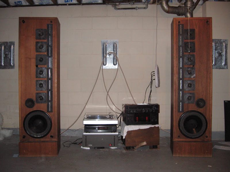
here's a pic i just took. forgive the messiness of the basement setup, i just threw it together. i'm using styrofoam for damping on the left. i'm going to experiment with moving the speakers further apart, as you can see in the background that i have plenty of wire left. i actually made some DIY cables in a jiffy for the woofers out of 18 Ga. solid copper wiring that i twisted for easier placement - my other decent wire is being used upstairs and wasn't handy. not sure how the DIY stuff is working, i'll do some A/B-ing at some point.
they sound really good. they're surprising delicate, and they don't sound "big" which is a good thing. the bass is tight as heck and as deep as you hear about. i'm impressed by female vocals and the accuract of piano reproduction. this is also the maiden voyage of my Denon DCD-1500II, and despite some problems reading certain CD-Rs and several other discs, i'm very happy with it. definitely seems to be an improvement in musicality over my ES changer, and i never noticed anything obviously lacking with that player.
here's a pic i just took. forgive the messiness of the basement setup, i just threw it together. i'm using styrofoam for damping on the left. i'm going to experiment with moving the speakers further apart, as you can see in the background that i have plenty of wire left. i actually made some DIY cables in a jiffy for the woofers out of 18 Ga. solid copper wiring that i twisted for easier placement - my other decent wire is being used upstairs and wasn't handy. not sure how the DIY stuff is working, i'll do some A/B-ing at some point.
Nikkoholic
Active Member
Awesome to see another happy QLS-1 owner. I have had mine for 31 years (youch) and they look like the day I bought them. You're right they are "a little" boxy but I just love the sound and don't know that I could get rid of them. Besides what to replace them with, similar specs today are just out of site $$.


banffskiing
Active Member
What kind of stuffing and how much did you use inside the speaker. I used about 4 lbs in each speaker.
i'm going to use raw unbleached cotton when i do the crossovers.
am i correct in remembering that the more you stuff in there, the tighter the bass, but you lose a little extension? i know these have the potential to bottom out before you run out of power, and that getting the right amount of stuffing is key to controlling that.
am i correct in remembering that the more you stuff in there, the tighter the bass, but you lose a little extension? i know these have the potential to bottom out before you run out of power, and that getting the right amount of stuffing is key to controlling that.
banffskiing
Active Member
hey
cdfac
Try the song by stabbing westward "WHAT DO i HAVE TO DO" the bass at the beginning of the song is unreal on the qls-1. can't even here anything comming from the laptop when i listen to the same song.
cdfac
Try the song by stabbing westward "WHAT DO i HAVE TO DO" the bass at the beginning of the song is unreal on the qls-1. can't even here anything comming from the laptop when i listen to the same song.
another update. the XO rebuild is in progress. i'm replacing everything except the three iron-core inductors in each speaker. you can find some pics and a parts list in the DIY thread i started here.
and yesterday i picked up a pair of basically the most monstrous, well-built, and (hopefully) sweet-sounding pro amps of all time: the PC5002M, as brought into our consciousness by Mark B. these ought to be enough power, i think :yes: i won't need to worry about active biamping any longer. i'll vertically biamp with one amp next to each speaker and have plenty of headroom left over. i already posted some nudies in Mark B's thread here. i have to do some cleaning up before they look decent, but a shot of the front is worth posting again:
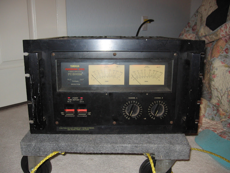
and yesterday i picked up a pair of basically the most monstrous, well-built, and (hopefully) sweet-sounding pro amps of all time: the PC5002M, as brought into our consciousness by Mark B. these ought to be enough power, i think :yes: i won't need to worry about active biamping any longer. i'll vertically biamp with one amp next to each speaker and have plenty of headroom left over. i already posted some nudies in Mark B's thread here. i have to do some cleaning up before they look decent, but a shot of the front is worth posting again:


Nikkoholic
Active Member
cdfac,
With that much power (and hopefully a little left over), how do you know when you reach the QLS-1 limit?
Also explain when you vertical biamp what do you use to get the signal to the amp? Long RCA cables? Do you have to worry about loss on these or is this less loss than with speaker wire delivering all that power to the speakers?
With that much power (and hopefully a little left over), how do you know when you reach the QLS-1 limit?
Also explain when you vertical biamp what do you use to get the signal to the amp? Long RCA cables? Do you have to worry about loss on these or is this less loss than with speaker wire delivering all that power to the speakers?
my plan right now is to use 4 8' RCA cables tipped with RCA->XLR adaptors. another option is to use only two of those into, say, the A channels, then use a short XLR cable to run from the amp's A channel output to the B channel input. i may also decide to use a Rane Balance Buddy to convert from RCA to XLR, in which case i'll definitely do something more like the latter. it's preferable to use longer interconnects than longer speaker wire, but i've read that you don't want to go longer than ~10ft with RCAs.
how will i know when i've reached the speakers' limit? when the woofers sound bad. i sincerely doubt that the amps will poop out first. i doubt i'll ever need the full RMS power of these, but i wanted the headroom so that i never have to burn out any EMITs while unknowingly clipping. i could've accomplished that with an active crossover, but the brute force power method means i don't have to deal with any extra noise or induced phase shifts.
how will i know when i've reached the speakers' limit? when the woofers sound bad. i sincerely doubt that the amps will poop out first. i doubt i'll ever need the full RMS power of these, but i wanted the headroom so that i never have to burn out any EMITs while unknowingly clipping. i could've accomplished that with an active crossover, but the brute force power method means i don't have to deal with any extra noise or induced phase shifts.
Nikkoholic
Active Member
cdfac,
Careful with all that power. I was crusing along with only 220/ch on top and 300w/ch on bottom with an active crossover and developed a "pop" in a brand new Watkins woofer (3 months old). Mr. Watkins feels it has been over driven, but never clipped or got any bad sound prior too. Now the pop seems to occur at even lower levels. (this concern/condition was posted in it's own thread)
We are still communicating on a solution, but likely I will send it to him to have it tested on the bench.
Just a heads up. I know you know infinity's like no else, but if that's what ultimately caused my problem I'd hate for you to experience the same.
Careful with all that power. I was crusing along with only 220/ch on top and 300w/ch on bottom with an active crossover and developed a "pop" in a brand new Watkins woofer (3 months old). Mr. Watkins feels it has been over driven, but never clipped or got any bad sound prior too. Now the pop seems to occur at even lower levels. (this concern/condition was posted in it's own thread)
We are still communicating on a solution, but likely I will send it to him to have it tested on the bench.
Just a heads up. I know you know infinity's like no else, but if that's what ultimately caused my problem I'd hate for you to experience the same.
Last edited:
banffskiing
Active Member
cdfac
Wow that's 2 much that amp is bigger than the clouthes basket. What kind of power does it produce.
Wow that's 2 much that amp is bigger than the clouthes basket. What kind of power does it produce.
banffskiing
Active Member
Do they have speaker protection built into the amp?