• The move to the new server is done. There are some software and database maintenance updates in process. This has us passing the hat around to help out. We appreciate any donations. Seriously, even a dollar helps. The payment page may be found here - https://www.audiokarma.org/support.html

KEF 107 Upgraded Xover, Size and impact on speaker volume

Jpkwd

Active Member
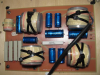
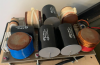
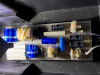
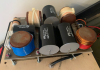
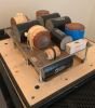
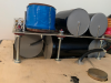
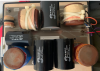
Having in mind to recap the crossovers of my kef 107, opening the cabs to have a look at the woofers crossover, i had the surprise (surpise might be an understatement, the shock might be more appropriate) of finding an upgraded crossover with Solen capacitors.

The seller did mention that the speaker had Solen capacitors in them, and i did not cross my mind that the size of these capacitors would be anything close to this :
upload_2020-10-29_11-18-19.png
upload_2020-10-29_11-20-45.png
upload_2020-10-29_11-19-1.png

It did put a smile on my face, don't get me wrong. I had no idea the Xover was rebuilt this way and i assume that caps equivalent to the Solen used should definitely be an improvement over stock Alcaps (i am assuming, and have not been in a position to compare with the original.

I would be curious of opinions on this upgrade ? Perhaps some AKer's have had the chance to compare the performances prior to an upgrade of this sort ? Would appreciate the feedbacks (note that woofers are also redone and all surrounds are replaced including the middle donuts)

My question would be around the impact of the foam job and volume of speaker cab in which the woofer operates.

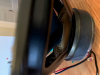
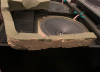
As you can see in the next pictures the foam has been dug out of to allow the speaker to "sit" in a cup that allwos the foam to be lowered and give a little room to the oversized caps. Man, they are definitely huge.

upload_2020-10-29_11-27-53.png
upload_2020-10-29_11-28-27.png

upload_2020-10-29_11-28-43.png

The original volume open space under the original unaltered foam has been reduced by the lowering of the foam board, which create an open unfilled space for the Xover over the foam (well, filled with new solen caps).

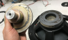
The magnet of the woofer is now sinked in the foam panel, and an increased volume of unfilled space exists above, and the volume of Air where the woofer was operating is reduced (by say 2-3 inches which is equivalent to the magnet depth).

on to the question : Would this change have any (positive of negative) impacts on the cab performance ?
 

Attachments

  • upload_2020-10-29_11-16-35.png
    upload_2020-10-29_11-16-35.png
    772.3 KB · Views: 40
  • upload_2020-10-29_11-17-16.png
    upload_2020-10-29_11-17-16.png
    747.5 KB · Views: 41
Register to hide this ad
Reading more on enclosure volume, or internal speaker volume, and quantity, presence or absence of damping material, i am wondering if the change has an impact that should be mediated :

1) The quantity of damping material (foam) has been reduced, which if my reading are right, has the equivalent impact of reducing the internal enclosure volume.
2) The size of caps used in the xover are non negligible, and also reduce the internal enclosure volume.
3) the lid has been grooved which increases slightly the internal enclosure volume, and is not equivalent to the space used by the caps.

Basically, the kef are two sealed enclosures (bottom and top) and one vented in the middle.
The top sealed encloure is being impacted by the mod, and has a reduced size compare to the bottom one.
upload_2020-11-27_11-53-5.png

https://jlaudio.zendesk.com/hc/en-u...ed-Enclosure-Characteristics?mobile_site=true

according to some simple analysis, By making the internal air volume smaller, the air spring exerts more control and limits cone motion at low frequencies, which increases power handling but does not let the system play as low and produces a more peaked response (higher Qtc.)

So i assume the current configuration of the xover to have an effect on low end response of the top sealed enclosure (less low end, or more controlled which will require more power to move the speaker), and a higher QTC.

Qtc - value for the damping provided for a driver in a sealed enclosure. Denotes the enclosures ability to control the driver response at resonance. Qtc = 0.707 is the optimum value for sealed enclosures, providing flattest response and highest SPL for deep bass extension. Enclosures for this value are often rather large. Lower Qtc can give even better transient response, down to a Qtc of 0.577 for the best damping and transients.

So in my case, higher QTC which lower transient response, damping and transient.

https://www.hometheaterforum.com/community/threads/what-does-qtc-mean.134990/
https://www.diyaudio.com/forums/multi-way/132096-reduce-speaker-cabinet-volume.html


Now Q factor can be a bit controlled with the Kube, but if modified a the enclosure level by the mod, the values displayed at the kube level probalby don't reflect the actual performance of the enclosure.

upload_2020-11-27_11-13-43.png


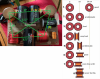
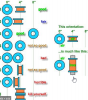
Another modification i have noticed today is that the coils orientations have been changed to be upright in two cases (blue and red wrapping on bottom two in the left pic, which is my xover).
and the resistors are stacked and connected in parallel (far left at bottom, my xover left image), which has no impact really i'm assuming aside from the top resistor say feeling the heat of the bottom one.

and we can judge the size of the new xover with the solen caps compared to the original. Huge caps really.

upload_2020-11-27_11-17-12.png

Rapid analysis, being no expert, i am not sure of the exact impact, there appears to be two problematic orientations for two coils (in red,refering to the coils placement guide from polkaudio, makes it more visual)
https://forum.polkaudio.com/discuss...oper-juxtaposition-of-inductors-in-crossovers

the mod has been done for space reasons, otherwise the coils in their original placement, would have been placed a bit outside of the board, and the xover would not have fitted in the enclosure.
the top left coil was moved, which created on problematic case, but the two lower ones are original placement.
and in the original stock form of the xover, all would be quoted as problematic according to this chart. So to be completely honest, i am not sure of the real impact of the modified coils placement in the modified xover.

upload_2020-11-27_11-39-44.png


So, with all that said, i am wondering if the 3 options i have are the following :

1) Leave everything as is, modified, and consider the impact on enclosure volume (missing foam, large xover) has very limited impact.
2) return the Xover to it's stock form ( I have the caps and i can modify it to be stock alcaps) and add the missing foam to the enclosure. Set the coils and resistor back to their original location.
3) Create an external xover enclosure, and move the xover to an external box. Add the foam back to the enclosure and wire to xover to the speakers. I can perform this without any mod to the enclosure and the possibility to return the speaker to its original state, without anyone knowing the mod ever happened. I have good quality wires to perform this change.

1 or 3 are evidently my favorite, since i'm keeping the solen caps in place.

I am starting to consider option 3, which appears like a good projet and can resolve the enclosure size challenge (if it has an impact, really, i am unsure of the magnitude of this impact).

Feedback absolutely welcome.
I definitely need help assessing this situation.
 

Attachments

  • upload_2020-11-27_11-14-35.png
    upload_2020-11-27_11-14-35.png
    309.4 KB · Views: 30
  • upload_2020-11-27_11-16-17.png
    upload_2020-11-27_11-16-17.png
    309.4 KB · Views: 23
  • upload_2020-11-27_11-16-41.png
    upload_2020-11-27_11-16-41.png
    847.5 KB · Views: 24
  • upload_2020-11-27_11-20-28.png
    upload_2020-11-27_11-20-28.png
    262.1 KB · Views: 23
  • upload_2020-11-27_11-21-55.png
    upload_2020-11-27_11-21-55.png
    174 KB · Views: 32
Calculating the volume of Caps to compare volume they use within the enclosure.


The solens take up about 10 times the volume of original caps:

293 inches3 vs 29 inches3.

upload_2020-11-30_10-0-26.pngupload_2020-11-30_10-0-50.png


Total volume difference between original xover caps and solen replacements : 264.76 inches3

Lid, or top panel, of the enclosure was modified with a router to create some volume to allow the solen xover to fit in : 27.34 inches3

Bottom line, i have a total of :

- 237.42 inches3 (3.89 Liters) of volume difference due to caps (reducing volume) and modified lid (augmenting volume)

- 220.82 inches3 (3.61 Liters) of missing foam that was removed to give some space for the solen loaded xover

the total bass enclosure internal volume per Kef specs is 72 Liters, and there are 3 sub sections in the encoluse (2 sealed enclosures sections with one ported section sandwiched between the to sealed ones).

i am assuming that the design represent and isobarik enclosure design if we do not consider the middle enclosure volume and consider the two woofers to be linked with the aluminum bar

if they are of the same volume, which i did not validate, then they would be both 24 liters in volume (72/3).

if my calculations are correct (not that i am sure they are unfortunately) :

Comparing the bottom sealed section with the top sealed section, there would be a difference of about 4 liters in volume, not considering the volume of foam removed (which if i understand correctly has the effect of increasing the volume of the enclosure from a design perspective, so missing foam also has the impact of reducing the volume of the speaker internal enclosure volume).
 
Last edited:
reading the following thread, https://audiokarma.org/forums/index.php?threads/the-kef-r107-cabinet-thread.450645/

the sealed chambers size appears to be exactly 285W X 405D X 190H(mm),
21930 cm3 or 21.93 Liter, a little less than the 24 Liters i assumed.

Another assumption is that both sealed chambers are of the same volume, 22L.
If my calculations are correct, the upper chamber with the Solen caps would be 18L compared to 22L for the bottom one.
Also, about 3.5L of damping foam would be missing in the upper chamber compared with the lower one.
 
Very nicely documented thread, with lots of clear pictures and diagrams.
And an interesting problem/dilema: Keep a (very expensive) upgrade or not?

By now,we must assume that the original capacitors would have drifted a bit - not as bad as a 1970's model - and would need a recap. Having said that, I am using the original crossovers in a frankenKEF 107 (more about this later on) and they sound just great.

The two loading chambers for the woofers should be of equal size (or actually compliance) to allow the two woofers to operate in symmetry and cancel each other's pressure. Otherwise, they would function like two different woofers mounted on the same shared sealed enclosure - the stronger woofer would take the weaker one on a ride. And since these two cavities are rather small, the tenfold increase in volume taken up by the crossover (did I get that right?) is important.

I agree with the three options you mention. What's hard is to decide which one to pick... Or perhaps devise a fourth one.

I would not go back to the original capacitors. And I would not feel comfortable with such a huge "monstrosity" taking up all that space on the upper chamber.

A few years back, having found the domes and crossovers, I built a pair of R107 inspired half breeds, copying the bass unit design and layout and using KEF B200 SP1014 (to keep some drops of family blood in them).
I made a few experiments and some calculations and ended up with 19lt as the cavity space. Not 22lt as your dimensions indicate. I started with the outer dimensions and scale and used much thicker plywood that was also lined with 6mm of bitumen sheets. Why am I mentioning this?

The easiest thing you can try to do is put 2 or 3 bottles of 0,5lt of water in the bottom chamber (filled with water) and see how that sounds, comparing the sound with the current setup. See if you hear any difference. I could measure difference in performance trying out different woofers on the given enclosure but I could not hear much difference between all of them. But could hear a difference comparing the best match and worst.

The enclosure volume is critical (well, almost) because in this band pass arrangement, it creates a huge notch at about 180Hz (IIRC) that a zobel network in the crossover is tuned to take down. If that peak moves higher (due to smaller volume of one enclosure), you get an audible peak between 180-200Hz.

What I would do is to build alternative crossover boards and use the soda can capacitors and air core inductors (as much as possible) on a separate box. Then use the binding posts of the loudspeakers to drive the woofers and drive the pods with separate cables. And then rebuild the original crossover PCBs to make them "factory".
 
thank you SaSi, appreciate the feedback a lot.

I have recapped the HF and MF enclosure xover with equivalent AlCaps, from a kit for R107 put together by falcon acoustics. A bit expensive, but I had the objective of setting the speakers back to factory specs.
This is how i can about the modified xover ("monstrosity" :) is quite a good way to describe the modded xover, i have to admit the solen caps are huge).
Here are before and after shots of the 107 heads :
upload_2020-12-1_13-5-2.png

upload_2020-12-1_13-4-42.png

I was left with the caps from the kit for the bass xover, and your suggestion to return the xover to it's original state in the bass enclosure makes sense to me. It would use the exact volume it was intended to use with the alcaps.
I would also correct the lid, perhaps make new ones in order to remove the groove that was made (which augments the volume of the top chamber).
And i have some foam i can put back in to get back to original volume.

So returning the box to its original state, with a factory crossover (which would be say "deactivated"), and Building a new crossover in a separate box sounds like a great plan to me.

One question
With the solution of having an external Xover, i was trying to figure out a way to avoid any new holes to the get from the Xover terminals to the woofers speakers.

Then use the binding posts of the loudspeakers to drive the woofers

Just to make sure i understand this right :

The crossover has connection for the lower and upper woofer (ULF and LLF negative and positive), which i understand are simply meant to reverting the phase between the two woofers (top one pushes down, bottom one pushes up).

building an exact replica of the factory crossover, I would be using one of the set of connections to the binding post (ex.: ULF + to positive binding post, ULF - to the negative binding post,
then sending the signal to the woofers (

+ Binding Post to ULF + and - LLF
- Binding post to ULF - and + LLF

upload_2020-12-1_13-15-18.pngupload_2020-12-1_13-15-31.png

Thanks a million for your response and feedback
 
You are correct about connecting the two woofers.
If you look at the picture of the crossover posts above, you will see that ULF+ and LLF- are on the same pcb trace. Same for ULF- and LLF+
 
Thanks for confirming Sasi,
After your comment, i did notice the Xover traces, and it made perfect sense.
that's the good part of my day. You really got me out of a rut there Sasi, i've been juggling with this challenge for some time now.

on the bad part of the day, i've definitely got bad luck unfortunately
And it is preventign me from testing the reduction of volume in the lower chamber of the speaker by adding uncompressible material like water bottles (to see if by balancing volumes in the two sealed enclosures the speaker would yield a change in sound).

I've got one of the SP1215 frozen, not budging at all...completely stuck...

for some reason it has a black frame, SP1215 badge, but is different than the 3 others that are working . Anyhow this one is not working at all currently.
upon disassembling the bass cab, i noticed the spider and checked for movement : none, the speaker is stiff.
Everything else is perfectly fine.

upload_2020-12-1_14-23-31.pngupload_2020-12-1_14-23-44.png

I'm reading 8.6 ohms at the speaker terminals.
and I read that in some cases the magnet slides which renders the speaker unusable without heavy lifting from a pro shop.

Or it a "simple" recone job

If ever you have a magic trick for this one, i'm a taker
or other variables to check before i either replace the speaker or have some work done in a specialized shop .
 
Plan is the following :

A) check all speakers
B) Return the enclosure to original state foam wise
C) Return the Xover to stock state
D) Create new external crossover with the Solen caps and new coils

A) Speakers : see previous post. I'll notify here what is the outcome on the speaker repair.
Rapid check with tech the magnet does not appear to be misaligned, and the speaker might be ok to be repaired. The cone flexes at one spot, like kinks right aside the donut at the center (once donut removed) when pushed.
That will require a bit of work on the paper cone to harden it, as the tech said. More to come on this later.
the 3 other speakers are in perfect shape.


B) Foam : I will simply say that whoever did the work on the enclosure when the speakers where refoamed and xovers upgraded had something for glue...
and did not want the foam to move...like at all. I will probably replace some foam with equivalent foam (suggestions welcome).

Doesn't need that much glue to hold foam firm...and not that kind of glue if you ask me.
upload_2020-12-2_17-17-54.png

C) Stock Crossover build : And the glory rolls on...
Coils, for some akward reason, probably to help glue them to the board in an upright position, were drilled.... ?
Unless i am mistaken, this removes some core and changes the value of the inductor.

But it did help to keep them in place...
I might have to replace these inductors too i guess...at least 3 of them. <

upload_2020-12-2_17-20-34.pngupload_2020-12-2_17-20-50.pngupload_2020-12-2_17-21-2.png


D) New Crossover : More to come later on this.
 
more on A) Speakers : Turns out i am facing the classic and well documented dried out glue slipping magnet syndrome with the woofer.

Here are photos sent by the tech :

the top plate could be removed, which is good news, and can be realigned and reglued to the magnet.
This is the reason why the coil was stuck

upload_2020-12-10_16-20-25.png

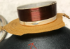
The coil shows signs of wear and displays a clear pinch at the location where to top plate was pinching it.

upload_2020-12-10_16-21-58.png

on to the bad news, the cone (and i have to admit this is my fault, when removing the center donut the paper cone was weakened). It cracked.
So a new paper cone will be most probably needed since gluing this cone back to avoid any issue later on seems risky.

It is right where the donut would be glued back though, but not so sure the glue would not have an effect on the performance of the driver, or would hold the paper cone correctly if applied on both sides.
That would probably add weight and be prone to failure. So a new cone appears to be appropriate.The question is will it match the specs of the other cones, and will the new spider be a good match (more stiff, more weight, etc)

upload_2020-12-10_16-26-24.png

I can't help to think : how long before another one fails ?
For now, i do not see any other choice than to repair the woofer and then try to look for upgrades (if that is even an option), or back up B250 speakers.
 
I am today wondering if there woudl be any preventive measure to avoid top plate slippage.
Like putting a bud of epoxy glue or similiar glue around the top plate of each speaker to secure the magnet and top plate.
There are metal Epoxies, and are pretty sturdy glues which could prevent the slippage, and give a bit more time before failing. Question is can this metal epoxy glue be even removed if needed.

These B250 speakers are next to impossible to source, and perhaps this calls for preventive measures, I am not sure.
and the repair will take weeks, so i get the feeling from the feedback from the tech who appears overloaded with work.

Another option goes along a cab and speakers upgrade completely getting rid of this aluminum rod which creates the dependency with the B250.
Clearly, those woofers are not up to par with the quality of the speakers.

@SaSi : i'll need to study your threads a bit more to see if this option is even remotely possible, keeping in mind the function of the rod which eliminates resonance of the cab.
I've got a set of B&W DM14 here which have heavy rubber panels inside the panels which perhaps would have a similar effect of preventing cabinet vibration if the rod is not there to prevent the "transfer of energy to the main enclosure".


upload_2020-12-20_10-42-28.png
 

Attachments

  • upload_2020-12-20_10-41-57.png
    upload_2020-12-20_10-41-57.png
    115.1 KB · Views: 4
My "Frankenstein" R107 resemble the bass enclosure design as much as possible. But I didn't have actual measurements, so I went by measuring stock photos of the cross sections and made them as close as possible. After that, I tried several different 8" woofers I had, all KEF.
I tried all that I have with 3 and 4 mounting holes. SP1014, SP1022, SP1039, SP1054, SP1063, SP1069, SP1070 and SP1075.
I tested them both mounted inside the enclosure and driven with the R107 crossover, as the bandpass enclosure creates a very "honky" frequency response with a brutal peak around 180Hz (IIRC).
The drivers I tried range from bextrene and impregnated paper cone, large and small magnet and 5, 8 and 16Ohms impedance.
The worst results were given by the large magnet drivers. And the paper cone ones were not loud enough. The SP1014, the oldest and humbler of the B200 variants gave the best results and they were great.
If you can fit a B200 4 screw driver over the existing openings, you would be fine.
I placed the drivers with both cones facing towards the shared cabinet and with magnets inside their own enclosures with wires phased the same to both drivers.
 
AK is on fire with R107 threads
Anyhoo
I think(i know) that XO is unnecessary big. What does this tell you ...usual thing audiophiles without EE knowledge to is to buy exotic caps of same value (god forbid they do +-10%) and copy n paste instead of educate themselves what could they do to existing XO that would suit their ROOm and equipment. Some caps on that XO really do not need to be polypropylene big types... Zobel network doesn't need anything more than lytics too ...instead of burning money on LF he should have spent it on HFMF . Really ... Anyway you're in process of learning now and hopefully you'll end up with a better speaker ...as for bass issues ....happened to the best of us too
 

Attachments

  • LF 1 + 2 nove.jpg
    LF 1 + 2 nove.jpg
    81.5 KB · Views: 36
  • DSC03418.JPG
    DSC03418.JPG
    94.1 KB · Views: 32
Hi
A quick question for more educated than myself ( most of you really ...lol) ... On original crossover there are two 100uF caps in parallel followed by inductor and that path leads to MF terminals . As you can s in photo in my previous post above those two were replaced by one HUGE Solen 200uF cap. All other caps were replaced by F&T bipolars (equivaent to Alcaps that Falcon sells as upgrade kit for 107 but I reckon better as F&T supplies Mundorf) . I am just curious why did the person working on upgrade chose to put polypropylen cap in that position alone? Im guessing because it feeds the signal to MF/HF head crossovers but who am I to tell. Just would like to know as he told me cost of those two was around 300$ so there must be some valid reason.
Thank you for your 2 cents.
 
To add my grain. of salt to this discussion about volumes. I am currently redrawing the 107/2 cabinets to ideal specs, not necessarely original ones.

The bottom cavity measures 285Wx405Dx190H for a volume of 21.93 litres or roughly 22 litres.
The upper cavity shall have the same volume, except for some corrections that must be done as you have noted. Volume of the crossover like you mentioned (29inch3 / 0.475 litres) but also volume of the driver "under the cone". Can we say another half liter?. Therefore, the upper cavity shall have an extra litre of volume.
My take is that the bottom cavity shall be 22 litres and the upper one shall be 23 litres, with stock crossover. Also, foam shall never be removed as it acoustically increases the volume of the cavity.
Is 23 litre for the upper cavity what you measured from your original 107.2 ?
 
As for the expen$$$ive Solen capacitors, I used them 30 years ago. Sure, the quality is there, but they are way too big and way too expensive. They are in my backyard but I have no motivation to buy any Solen cap anymore.
 
Back
Top Bottom