• The move to the new server is done. There are some software and database maintenance updates in process. This has us passing the hat around to help out. We appreciate any donations. Seriously, even a dollar helps. The payment page may be found here - https://www.audiokarma.org/support.html

Kegger/blueglow kt88 project

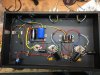
I'm finishing up my build, only a few more evenings before I get to test it! I thought I would share the progress for any feedback before I install the last few components. https://imgur.com/a/PCJE414
Thanks guys.

Really Nice, what great attention to detail ! Not only does it look great, I have already found the neater and more precise the easier to change/repair in the future. I like the spacing of the of the electrolytics, I had an issue where I overheated a solder joint and melted the cap insulation and caused a short. Enjoyed viewing your pics. Is that a thermistor near the iec or are you running without one, can't clearly see.
 
Last edited:
Really Nice, what great attention to detail ! Not only does it look great, I have already found the neater and more precise the easier to change/repair in the future. I like the spacing of the of the electrolytics, I had an issue where I overheated a solder joint and melted the cap insulation and caused a short. Enjoyed viewing your pics. Is that a thermistor near the iec or are you running without one, can't clearly see.
Thanks Bill. Yes, I am using a thermistor. It connects after the fuse, but before the power switch.
 
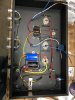
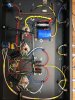
amp1.jpg amp3.jpg Hello, I have started to build the Blueglow KT88 amp...however ran into an issue blowing fuses. The PS works great 576V unloaded but when attached to KT88...not so much. I have attached a couple pics. If anyone can spot something I would really appreciate feedback. I have checked & rechecked but need some help.....thanks
 
I can't see anything by looking at the pictures. If the fuse blows right away it usually points to a short. If it takes a few seconds it points to sustained high current. Do you have any way to identify high current, such as a dim bulb tester? Since you say it powers up fine without power tubes I would focus on the wiring going to the output tube sockets.
 
View attachment 1475035 View attachment 1475037 Hello, I have started to build the Blueglow KT88 amp...however ran into an issue blowing fuses. The PS works great 576V unloaded but when attached to KT88...not so much. I have attached a couple pics. If anyone can spot something I would really appreciate feedback. I have checked & rechecked but need some help.....thanks

First Wow, beautiful build, looks wonderful.

My advice is start with the simple, my issue was a combo of things, I had a wire (twice) pinched under the power transformer, there is zero room for a wire under the transformer, when I tightened it down it cut the insulation, second while messing with it the ground on the iec had broken off and moved ever so slightly to rest on the neutral lug, looked good but made the GZ34 go crazy shorting sounds buzzing etc, actually wrecked one brand new tube. I carefully unbolted and looked under the transformer and I thought I had pulled the wires through the grommet but not all. I actually took the ps apart and redid it and pinched another wire, sheesh, once this beast is assembled pulling the ps transformer is easier said than done. I did accidentally melt the bottom insulation on one of the 33uf caps, not sure if was shorting but redid and left more space.

I even tried disconnecting wiring in an attempt to isolate the problem, you might give it a try, mine would work when slowly brought up on the variac but if switched on with full ac it would make that sound and blow the fuse. One thing is for sure you have a short somewhere. Does it blow the fuse with the B+ disconnected to the KT88's? Maybe try disconnect one at a time B+ to the KT88's, and alternate. What does the heater voltage measure with no tubes? Discharge the ps caps and try to measure any of the transformer wiring to ground.

This thing cost me a lot of sleep but works great now, you'll find it, don't give up..

And of course what JohnT123 said!
 
Last edited:
The no load B+ value seems quite high to me. Unfortunately I didn't build my amp like Marks and I used different transformers. I'd be interested to see what the numbers are like compared to another made the same way, with the same parts. I notice that Twirl has made his a bit different from the original. He built his without the T/P circuitry. I'm about to dive into Version 2. I should post my circuits in case anyone can spot design mistakes or suggest improvements. Probably best to start a new thread for that. I also need to find some way of creating and printing the schematic.
 
The no load B+ value seems quite high to me. Unfortunately I didn't build my amp like Marks and I used different transformers. I'd be interested to see what the numbers are like compared to another made the same way, with the same parts. I notice that Twirl has made his a bit different from the original. He built his without the T/P circuitry. I'm about to dive into Version 2. I should post my circuits in case anyone can spot design mistakes or suggest improvements. Probably best to start a new thread for that. I also need to find some way of creating and printing the schematic.

My no load b+ was 585, his isn't out of line with mine, if I remember right Mark's on his video was also in the 580v +/- range.

Got my new chassis in, have the power transformer, waiting on the others, got the hammond with the walnut end panels, this will hopefully be a more precise build, mounting the transformers with 3/8 grommets with a stainless tube insert, vu meters, painted endbells etc, should be fun.

Glutton for punishment I guess.
 
The no load B+ value seems quite high to me. Unfortunately I didn't build my amp like Marks and I used different transformers. I'd be interested to see what the numbers are like compared to another made the same way, with the same parts. I notice that Twirl has made his a bit different from the original. He built his without the T/P circuitry. I'm about to dive into Version 2. I should post my circuits in case anyone can spot design mistakes or suggest improvements. Probably best to start a new thread for that. I also need to find some way of creating and printing the schematic.

Take a look at Digi-Key, they have free schematic software all the symbols etc.
 
Thanks Bill, I didn't know that was available. I'll have a look.

Is your next build going to be the same as your first or are you changing things? In my case I'm simplifying a couple things and I'm trying different coupling caps. I used the cheapest Mundorf EVO caps on this amp. The next one will have the Mundorf Silver,Gold,Oil EVO caps. I'm eliminating the standby switch and replacing 2, 20uf caps with 1, 39uf cap. So not a lot of change. I also have to choose between a regular power transformer and a toroidal with a bit higher high voltage from the secondary.
 
Thanks Bill, I didn't know that was available. I'll have a look.

Is your next build going to be the same as your first or are you changing things? In my case I'm simplifying a couple things and I'm trying different coupling caps. I used the cheapest Mundorf EVO caps on this amp. The next one will have the Mundorf Silver,Gold,Oil EVO caps. I'm eliminating the standby switch and replacing 2, 20uf caps with 1, 39uf cap. So not a lot of change. I also have to choose between a regular power transformer and a toroidal with a bit higher high voltage from the secondary.

I played with the Dig-Key schematic creator and found it to be very cool. I intend to make some changes, higher quality all around. Lots of mechanical improvements, like you some upgrades in caps, vu meters, just overall attempting for a very high quality assembly, will also add ventalation holes, guess some are cosmetic but want to see how perfect I can build one. Did you say you had invested in a discovery? I am also getting ready for the preamp build learning how to make the walnut end panels for different depth chassis, wish hammond sold them separate.

I guess the next build will be the pursuit of perfection, not sure I can achieve it but want to try.
 
On this amp I had a friend make the wooden side panels and it was expensive. For #2 I bought the chassis with the walnut end panels to save money. They don't look as nice but it saved me enough to pay for the higher end caps. I contacted Hammond about separate end blocks but they didn't even return my email. :bs:
 
On this amp I had a friend make the wooden side panels and it was expensive. For #2 I bought the chassis with the walnut end panels to save money. They don't look as nice but it saved me enough to pay for the higher end caps. I contacted Hammond about separate end blocks but they didn't even return my email. :bs:

I also bought the 4 inch deep chassis with wooden end panels, I also have a grey 3 inch chassis I'm saving for the pre amp build. I experimented with my router table and was able to make end panels. I have ordered some walnut so will see. I had also contacted Hammond for a non powder coated chassis but I would have to buy 10 minimum, was thinking of a hammered finish but no joy. Guess I could have a chassis sandblasted but not sure it would work. Where did you get the higher end caps?

here is what I'm thinking for the new build layout:

Layout 2.jpg
 
Last edited:
I finished by build over the weekend. I added a few photos to the imgur gallery above.
This thing sounds great!
When selecting LED's for voltage drop, I was only able to find some at 1.58v drop, not the 1.4 to 1.5 as in the spec. What effect would this have on the amp?
 
I finished by build over the weekend. I added a few photos to the imgur gallery above.
This thing sounds great!
When selecting LED's for voltage drop, I was only able to find some at 1.58v drop, not the 1.4 to 1.5 as in the spec. What effect would this have on the amp?

Very nice job, nice attention to detail, shows pride of build. As long as they are closely matched you're in great shape. I actually built a bench power supply and had a little more control the second time around, especially on the current, think mine ended up at 1.46 drop. You are exactly where Mark was in the videos, 1.57 v and I believe he said he was going with that, everything is so close that even the meters you use (I use) can throw it off a little.
 
Last edited:
Very nice job, nice attention to detail, shows pride of build. As long as they are closely matched you're in great shape. I actually built a bench power supply and had a little more control the second time around, especially on the current, think mine ended up at 1.46 drop. You are exactly where Mark was in the videos, 1.57 v and I believe he said he was going with that, everything is so close that even the meters you use (I use) can throw it off a little.

Thanks Bill, The LED's are within 0.002 volts of each other at 5.05mA
 
Thanks Bill, The LED's are within 0.002 volts of each other at 5.05mA

Sounds too close to make any difference, I have one DMM that reads a hair low (I think) and one that reads a hair high, wish I had perfect test equipment but when you think about it even the tolerances on the components make a little change. Well get some hours on it, whats next?

BTW some neat pics of those tubes a glowing!
 
Hello Guys! I'm a newbie, and i'm collecting parts for this project (first one). Thinking about changing some parts, like the transformers, i'm going for a set of toroidal transformers, and i want to make a more traditional approach at the cathode of the ECC85. I'have been working on the lay out diagram. can some one validate my wiring scheme, i'm a little worried about the grounding part. Oh i'm Portuguese so excuse me, if my writing is poor, thanks.ECC85 - KT88 - V2.png
 
Hello Guys! I'm a newbie, and i'm collecting parts for this project (first one). Thinking about changing some parts, like the transformers, i'm going for a set of toroidal transformers, and i want to make a more traditional approach at the cathode of the ECC85. I'have been working on the lay out diagram. can some one validate my wiring scheme, i'm a little worried about the grounding part. Oh i'm Portuguese so excuse me, if my writing is poor, thanks.View attachment 1480919

Very nice, like the layout, what software did you use to draw your layout, very cool. Looking forward to watching your progress. I am waiting on transformers and a few parts, I may start drilling the chassis this weekend. I'm sure thee experts will chime in on your design, what do you estimate your B+ will be with this setup,, I can't read the numbers on the transformers, in fact I can't read anything, when I blow it up it gets so distorted it's unreadable to me.
 
Last edited:
Back
Top Bottom