


You are using an out of date browser. It may not display this or other websites correctly.
You should upgrade or use an alternative browser.
You should upgrade or use an alternative browser.
Kegger/blueglow kt88 project
- Thread starter Tubeglowpio
- Start date

primosounds
Powered with pure tube sounds.
A bad OPT can be a real pain when it is in circuit. Hopefully that is not your issue. At least you are closing in on your problem.Well, I resoldered every connection last night, blew the fuse when I hit it with straight ac out of the outlet, I guess the variac nurseses it.
I decided to try to isolate (Divide & Conquer) it so disconnected the B+ to the amp side, no blown fuses, connected the B+ without the OPT's hooked up, still no blown fuses. Connected the Right channel, no blown fuse and got my tone. Connected the left channel and zap, lost a fuse. I now know where to look.
My wife is commenting how much more patience I am learning, sigh

Ruidoso Bill
Active Member
Not good enough, I'm going backwards, the more I do the worse it's getting. This pic was from earlier on one of the PS caps
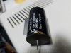
I am about to unsolder everything and start over, something is way amiss here.
Last edited:
Ruidoso Bill
Active Member
A bad OPT can be a real pain when it is in circuit. Hopefully that is not your issue. At least you are closing in on your problem.
I just don't know anymore, new OPT's from Edcor.
I have also loosend up all the transformers looking for a crimped wire etc and see no signs of that.
Ruidoso Bill
Active Member
Have you double checked the UL switch for correct in and out?
I have gone over everything, I am thinking of wiring it up in triode mode, eliminat a bunch of wiring to test it more simply, i just don't know what to do next.

JohnT123
Super Member
I'd disconnect the transformers and check the DC resistance on each one to see if they are different. Edcor does have a bulletin cautioning people not to stress or over twist the leads because of possible shorts or open winding's. One side of your B+ filter cap could be shorted, there are a lot of things it could be. I'd start taking test measurements on you components and see what's failed. When you check the wiring get in there with a good light and magnifier. I've seem all sorts of hard to spot grounds and shorts. Your problem is right in front of you waiting to be found. I'd separate the circuit into small blocks and just work through each one. If there are no faulty components then the fault must be in the way they're connected together.
Ruidoso Bill
Active Member
I'd disconnect the transformers and check the DC resistance on each one to see if they are different. Edcor does have a bulletin cautioning people not to stress or over twist the leads because of possible shorts or open winding's. One side of your B+ filter cap could be shorted, there are a lot of things it could be. I'd start taking test measurements on you components and see what's failed. When you check the wiring get in there with a good light and magnifier. I've seem all sorts of hard to spot grounds and shorts. Your problem is right in front of you waiting to be found. I'd separate the circuit into small blocks and just work through each one. If there are no faulty components then the fault must be in the way they're connected together.
I used a small plastic clamp to hold the wires after reading the caution about twisting. I also use a lighted magnifier to inspect and see while I work and review. Maybe tomorrow with fresh eyes things will be more clear, maybe I just need to take a break. Without the B+ hooked up on the amp side it doesn' blow the fuse and will run all day.
Thanks John for the suggestions, much appreciated.
Last edited:
Ruidoso Bill
Active Member
I'd disconnect the transformers and check the DC resistance on each one to see if they are different. Edcor does have a bulletin cautioning people not to stress or over twist the leads because of possible shorts or open winding's. One side of your B+ filter cap could be shorted, there are a lot of things it could be. I'd start taking test measurements on you components and see what's failed. When you check the wiring get in there with a good light and magnifier. I've seem all sorts of hard to spot grounds and shorts. Your problem is right in front of you waiting to be found. I'd separate the circuit into small blocks and just work through each one. If there are no faulty components then the fault must be in the way they're connected together.
Doesn't DC Resistance require a special tester?
Ruidoso Bill
Active Member
I'd disconnect the transformers and check the DC resistance on each one to see if they are different. Edcor does have a bulletin cautioning people not to stress or over twist the leads because of possible shorts or open winding's. One side of your B+ filter cap could be shorted, there are a lot of things it could be. I'd start taking test measurements on you components and see what's failed. When you check the wiring get in there with a good light and magnifier. I've seem all sorts of hard to spot grounds and shorts. Your problem is right in front of you waiting to be found. I'd separate the circuit into small blocks and just work through each one. If there are no faulty components then the fault must be in the way they're connected together.
Resistance readings OPT
Right Blue "Plate" red "B+" = 85.8 ohms, Red "B+" to Blue/White "Screen" = 54.5 ohms, Blue "Plate" to Blue/White "Screen = 33.5 ohms, Outputs Yellow & White = 2.5 ohms
Left Blue "Plate" red "B+" = 86.5 ohms, Red "B+" to Blue/White "Screen" = 54.8 ohms, Blue "Plate" to Blue/White "Screen" = 33.8 ohms, Outputs Yellow & White = 2.5 ohms
Both transformers appear nearly identical, no wire twisting on these.
Resistance readings OPT
Right Blue "Plate" red "B+" = 85.8 ohms, Red "B+" to Blue/White "Screen" = 54.5 ohms, Blue "Plate" to Blue/White "Screen = 33.5 ohms, Outputs Yellow & White = 2.5 ohms
Left Blue "Plate" red "B+" = 86.5 ohms, Red "B+" to Blue/White "Screen" = 54.8 ohms, Blue "Plate" to Blue/White "Screen" = 33.8 ohms, Outputs Yellow & White = 2.5 ohms
Both transformers appear nearly identical, no wire twisting on these.
Last edited:
Ruidoso Bill
Active Member
I'd disconnect the transformers and check the DC resistance on each one to see if they are different. Edcor does have a bulletin cautioning people not to stress or over twist the leads because of possible shorts or open winding's. One side of your B+ filter cap could be shorted, there are a lot of things it could be. I'd start taking test measurements on you components and see what's failed. When you check the wiring get in there with a good light and magnifier. I've seem all sorts of hard to spot grounds and shorts. Your problem is right in front of you waiting to be found. I'd separate the circuit into small blocks and just work through each one. If there are no faulty components then the fault must be in the way they're connected together.
Resistance readings OPT
Right Blue "Plate" red "B+" = 85.8 ohms, Red "B+" to Blue/White "Screen" = 54.5 ohms, Blue "Plate" to Blue/White "Screen = 33.5 ohms, Outputs Yellow & White = 1.5 ohms
Left Blue "Plate" red "B+" = 86.5 ohms, Red "B+" to Blue/White "Screen" = 54.8 ohms, Blue "Plate" to Blue/White "Screen" = 33.8 ohms, Outputs Yellow & White = 1.5 ohms
Both transformers appear nearly identical, no wire twisting on these.
Last edited:
primosounds
Powered with pure tube sounds.
Since both trannys have the same resistances it is not a likely problem, although sometimes under load or full voltage a short can show up. But that would mostly be on a very old transformer where corrosion has created some insulation of the short to the chassis. If you are desoldering suspect parts try using test leads between components when you put them back in circuit. If the fuse blows you have your bad part, if it doesnt then you are good. This is true if the circuit has checked.Resistance readings OPT
Right Blue "Plate" red "B+" = 85.8 ohms, Red "B+" to Blue/White "Screen" = 54.5 ohms, Blue "Plate" to Blue/White "Screen = 33.5 ohms, Outputs Yellow & White = 1.5 ohms
Left Blue "Plate" red "B+" = 86.5 ohms, Red "B+" to Blue/White "Screen" = 54.8 ohms, Blue "Plate" to Blue/White "Screen" = 33.8 ohms, Outputs Yellow & White = 1.5 ohms
Both transformers appear nearly identical, no wire twisting on these.
I have found that when i have an issue similar to yours, i mostly incorrectly wired a tube socket, which is very easy to do.
Ruidoso Bill
Active Member
I'd disconnect the transformers and check the DC resistance on each one to see if they are different. Edcor does have a bulletin cautioning people not to stress or over twist the leads because of possible shorts or open winding's. One side of your B+ filter cap could be shorted, there are a lot of things it could be. I'd start taking test measurements on you components and see what's failed. When you check the wiring get in there with a good light and magnifier. I've seem all sorts of hard to spot grounds and shorts. Your problem is right in front of you waiting to be found. I'd separate the circuit into small blocks and just work through each one. If there are no faulty components then the fault must be in the way they're connected together.
Choke = 1 ohm
Power transformer
Primary measures 1.5 ohms
Secondary red to red = 86 ohms, red/black CT to both reds 45 ohms
Brown & Brown 6.3 heaters = 1.2 ohms
Yellow & Yellow 5v 1.5 ohms
Nothing to ground from any wire
Ruidoso Bill
Active Member
Since both trannys have the same resistances it is not a likely problem, although sometimes under load or full voltage a short can show up. But that would mostly be on a very old transformer where corrosion has created some insulation of the short to the chassis. If you are desoldering suspect parts try using test leads between components when you put them back in circuit. If the fuse blows you have your bad part, if it doesnt then you are good. This is true if the circuit has checked.
I have found that when i have an issue similar to yours, i mostly incorrectly wired a tube socket, which is very easy to do.
I almost have it all apart again, can't measure things at all if still in circuits, I noticed on the nine pin socket I buggered it up between a couple with some solder drip, I did my best to clean it up, no continuity and neither measured anything to ground but it looked a little shabby, $2.25 not worth worrying about.
I went ahead and removed the nine pin socket, all the associated wiring resistors caps etc, I have ordered it all new since it's the cheap stuff anyway. the 8 pins remain pretty much in tack but a lot easier to examine.
When I start putting it back together, one step at a time, make sure the ps is working and not blowing anything, hook up the heaters, one channel at a time.
I am even replacing the fuse older with a regular size 30mm fuses which are easy to get, I had one of the 20mm ones and those are not so easy to find and required ordering.
JohnT123
Super Member
The transformer measurements are really just indicators of open winding, shorts or imbalances. Yours look good to me. My order of operations when wiring is to build the power supply and then wire the filaments. At that point I test everything I've done. If it's all good then I wire all the high voltage connections to the tube sockets and test again. When I started building guitar amps I made the mistake of building the entire amp before I turned it on for testing. Big mistake. By completing a section and testing, it makes it much easier to tell where and when something went wrong. You'll get it sorted.
Ruidoso Bill
Active Member
The transformer measurements are really just indicators of open winding, shorts or imbalances. Yours look good to me. My order of operations when wiring is to build the power supply and then wire the filaments. At that point I test everything I've done. If it's all good then I wire all the high voltage connections to the tube sockets and test again. When I started building guitar amps I made the mistake of building the entire amp before I turned it on for testing. Big mistake. By completing a section and testing, it makes it much easier to tell where and when something went wrong. You'll get it sorted.
I appreciate your input, slow and methodical this next time, as long as I don't get too excited!
Last edited:
Ruidoso Bill
Active Member
So now it's waiting for the UPS delivery, my new brother-in-law gave me a new/used scope, wow, both channels work. Cleaned up my work area, gotta do something without parts. I'm ready, bring on your worst Mr. SET, clean mind, fresh start, life is good.

Ruidoso Bill
Active Member
I really want to know how this story ends
Me too.
Sometime when you get a few I'd love to hear about your guitar amps.
primosounds
Powered with pure tube sounds.
Hi Bill. I can appreciate wanting to redo everything or nearly everything from your defective amp. But,There is no guarantee that you will have any better luck. You might repeat the same error and therefore achieve the same result. I guess it is too late now, but, in trying to troubleshoot a problem by replacing a bunch of parts is not going to answer the question of what was wrong with the original amp.I almost have it all apart again, can't measure things at all if still in circuits, I noticed on the nine pin socket I buggered it up between a couple with some solder drip, I did my best to clean it up, no continuity and neither measured anything to ground but it looked a little shabby, $2.25 not worth worrying about.
I went ahead and removed the nine pin socket, all the associated wiring resistors caps etc, I have ordered it all new since it's the cheap stuff anyway. the 8 pins remain pretty much in tack but a lot easier to examine.
When I start putting it back together, one step at a time, make sure the ps is working and not blowing anything, hook up the heaters, one channel at a time.
I am even replacing the fuse older with a regular size 30mm fuses which are easy to get, I had one of the 20mm ones and those are not so easy to find and required ordering.

invaderzim
Super Member
I built this amp once (stereo) then sold it. After experimenting with several other amps since then (6BQ5 SE) & considering a DHT, I’ve decided to build another. Only this time, more simplified in the mode I preferred. For starters, no bias switch, triode only, EL-34, 15 watt GXSE OPT.
I’m really interested in the mono-bloc & separate PS discussion. I think both ideas would take this amp beyond ultimate.
I’m gonna enjoy following this thread!
Are you going to go with feedback on this build? I didn't have it for the longest time on mine because I read several things saying with it wired as a Triode it didn't need it in that low of power but after adding it per the kegger schematic I noticed a real improvement in the sound.