• The move to the new server is done. There are some software and database maintenance updates in process. This has us passing the hat around to help out. We appreciate any donations. Seriously, even a dollar helps. The payment page may be found here - https://www.audiokarma.org/support.html

Kegger/blueglow kt88 project

You can chase that but if you are getting 10.5w, no need. If you were clipping at 4W, then yes. Nice looking build BTW.
Thanks for the comment. I would never have attempted this without your excellent video series. I have been an electronics tinkerer all my adult life even though my career work was in IT for the aerospace research industry. Just now getting back into audio and tube stuff since I retired. I am connecting it up today to my K-Horn clones I built back in the 1980's from Speakerlab. I recapped the crossovers and have been using them in my shop driving with a NAD 3020. I am so happy how the amp is working just driving some old RS bookshelfs I can't wait to here it on more efficient speakers.

Again, thanks for your excellent videos!!
 
I find it comical that a group of experts on DIYAudio are claiming: from their calculation and sims this amp can only produce 5W at best and is a horribly designed, high distortion amplifier that is 1/2 of a class AB amp built as a "all show and no Go" toy. So many people have actually built this amp and bench tested it at 10W+ and seen the low distortion it has, myself included. Plus we all know how good this amp sounds.

I know if my calculations/simulations didn't match what actual testing proved, I would be revisiting my calculations/simulations rather that proclaiming the people who have built this amp and bench tested it were pushing some fraudulent agenda.
 
I find it comical that a group of experts on DIYAudio are claiming: from their calculation and sims this amp can only produce 5W at best
I don't recall reading about anyone who has built and tested this amp getting anything less than 10 watts rms into 8 ohms. I could get 13.5 watts into a 5 ohm load before clipping. I don't have the hardware to test distortion, but it really sounds good to my old ears! It seems there are a lot of people spending a lot of time proving they can run simulation software but not any time showing their own builds. In the industry I retired from (aerospace research), all the major aircraft companies run simulations early in the design stage. However, they all spend millions on all sorts of wind-tunnel models to test their simulations. I would much rather spend by money building to a design that many people have built and liked than one based on someone's simulations. But that's just me/
 
You likely remember the old quote of Daniel von Recklinghausen the famous Scott engineer from the tube glory days. Maybe now the term "measures" should be changed to "simulated".
"If it measures good and sounds bad, -- it is bad. If it sounds good and measures bad, -- you've measured the wrong thing."
 
Please don't take me wrongly. I use simulations.
I do also. I only wish I was better at it. I certainly do not intend any disrespect to those who know how to use simulations. I have tried PSUD and a couple of load line graphing apps. I have been tinkering with electronics for 50 years but for some reason have not really explored any of the full blown circuit simulation programs. I am using KiCad and EasyEDA currently and before I retired I used some really expensive electronics design software all of which I think have the ability to interface with circuit simulation software. Maybe I should spend a little time trying it out. To be honest, most of my circuit designs are microprocessor based circuits and they usually either work or not. Not much in the analog world. Tube based amps are about as analog as you can get!
 
Please don't take me wrongly. I use simulations. They are a useful tool. You just can't blindly assume that they give you the absolute truth.
Enjoy your amps.
John

Right. When I am designing an amp, I calculate what resistors I need to get the voltages I want to see and simulate power supplies etc but that is never a replacement for actually measuring the voltages on power up. Right now I am dealing with a simulator that predicted a different result on the power supply output than I got on the built amp. I'm not going to just say "Well that can't be happening because I calculated a different result" lol.

It's the same with distortion and power output, especially with tube circuits.
 
One of the things Kegger used to say was that he'd design/simulate an amp, build it, and consider that a "starting point". He'd update the tube models in the sim to reflect what they did in the circuit in front of him, and adjust the resistors accordingly. He said it got him within 10-20% of the real world a lot of the time.

He also didn't shy away from objective metrics. In particular I think this design is the most measured of any of his, both by him and others. He wasn't invested in any particular design, he was more interested in what worked, and was always looking to improve/mod his designs. To think that he was dogmatic in his approach is laughable.

None of my comments are responding to anyone in particular here, I've had a contemplative morning and my mind has wandered...
 
This is an interesting discussion and what everyone has said really mirrors my approach and is actually what I like about tube amps which is that you can understand and design them with a pen, paper and a calculator. If some people are claiming it's only 5W then they don't understand the basics of tube operation and have never looked at the KT88 data sheet. Having said that it would be nice to have a simulator that did a good job simulating tube amp circuits; it's not at all clear that all the various unsupported tube models out there (e.g. for Spice) have been validated well.

What impresses me most about the Kegger amp is that it is simple, easy to build and sounds very good for the amount of money you have to invest. I don't think anyone expects this to be the "ultimate" power amplifier design but it works really well within the design constraints.
 
Hi again folks.
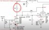
OK, so my SE KT88 is working nicely. But I had cause to move it the other day, happened to turn it over in the process, and noticed that the two 39K ohm plate load resistors were a little toasty. Now my resistors were mostly cheap and cheerful Chinese metal films, supposedly rated at 2 watts, and I have about 218v across these resistors, so 5.6mA, so about 1.25W of power dissipation; theoretically all good. But as I said - toasty. So I've now got some 7W resistors to swap those ones out. Just keeping you up to speed!
Have fun, Simon

Circuit.JPG
39K R.jpg
 
I've seen discoloration like this even with name brand resistors. Regardless of the source, I generally size resistors for not less than 3X the expected dissipation. These particular resistors should be OK with a 3W rating. That seems to be a commonly needed size, and I keep a lot on hand in various values. Larger wattage resistors also have a higher voltage rating, which is never a bad thing in tube circuits. Your 7W resistors should last the life of the amp.

Jack
 
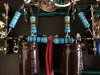
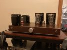
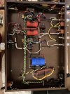
Hey All. Just finished my build and figured I'd share. This thread was definitly very helpful, so thanks to all for sharing their tips and tricks. Its mostly stock to how Mark built his, but a few simple additions.

-Powder coated the chassis and transformer bells.
-Added 1/8" steel plates to the bottom to add more legit feet, and helps a lot to keep the chassis sterdy with the weight of the transformers.
-Bleeder resistors for the power supply caps.
-Jupiter caps for everything within the audio path.
-I added StepheK's "tube headphone box" cicurit, but built it within the chassis as oppose to a seperate enclosure. Speaker or headphone output can be selected via the back with a DPDT switch. Its a very easy to add feature and sounds great. Big thanks to StepheK as well. Her youtube channel/website is truely an amazing resource of knoweldge.

Only minor issue like many have seemed to experience here is some hum from the Edcore PT. I bought there silicon mounting pad hoping that would help, but its still a bit noticeable. Luckily, its not really present in the audio signal, just kind of distracting when around the amp. I may try and troubleshoot that later, but for now its not bugging me enough to not enjoy the amp.

Thanks to Mark as well for helping create such a fun and approoachable project.
 

Attachments

  • IMG_1573.jpg
    IMG_1573.jpg
    76.3 KB · Views: 91
  • IMG_1570.jpg
    IMG_1570.jpg
    163.5 KB · Views: 92
Hey All. Just finished my build and figured I'd share. This thread was definitly very helpful, so thanks to all for sharing their tips and tricks. Its mostly stock to how Mark built his, but a few simple additions.

-Powder coated the chassis and transformer bells.
-Added 1/8" steel plates to the bottom to add more legit feet, and helps a lot to keep the chassis sterdy with the weight of the transformers.
-Bleeder resistors for the power supply caps.
-Jupiter caps for everything within the audio path.
-I added StepheK's "tube headphone box" cicurit, but built it within the chassis as oppose to a seperate enclosure. Speaker or headphone output can be selected via the back with a DPDT switch. Its a very easy to add feature and sounds great. Big thanks to StepheK as well. Her youtube channel/website is truely an amazing resource of knoweldge.

Only minor issue like many have seemed to experience here is some hum from the Edcore PT. I bought there silicon mounting pad hoping that would help, but its still a bit noticeable. Luckily, its not really present in the audio signal, just kind of distracting when around the amp. I may try and troubleshoot that later, but for now its not bugging me enough to not enjoy the amp.

Thanks to Mark as well for helping create such a fun and approoachable project.
Super nice build!! :)
 
Very well done, looks better than mine I think :)
Stay tuned, I'll make a post on how to tame that Power Transformer hum...

Hey All. Just finished my build and figured I'd share. This thread was definitly very helpful, so thanks to all for sharing their tips and tricks. Its mostly stock to how Mark built his, but a few simple additions.

-Powder coated the chassis and transformer bells.
-Added 1/8" steel plates to the bottom to add more legit feet, and helps a lot to keep the chassis sterdy with the weight of the transformers.
-Bleeder resistors for the power supply caps.
-Jupiter caps for everything within the audio path.
-I added StepheK's "tube headphone box" cicurit, but built it within the chassis as oppose to a seperate enclosure. Speaker or headphone output can be selected via the back with a DPDT switch. Its a very easy to add feature and sounds great. Big thanks to StepheK as well. Her youtube channel/website is truely an amazing resource of knoweldge.

Only minor issue like many have seemed to experience here is some hum from the Edcore PT. I bought there silicon mounting pad hoping that would help, but its still a bit noticeable. Luckily, its not really present in the audio signal, just kind of distracting when around the amp. I may try and troubleshoot that later, but for now its not bugging me enough to not enjoy the amp.

Thanks to Mark as well for helping create such a fun and approoachable project.
Great looking amp inside and out! Mine also has a slight mechanical hum From the Edcor XPWR033 power trans (since day one.). Still love the sound! Looking forward to Mark’s reply on how to tame!
 
Super nice build!! :)
Thanks! Just got custom transformers from Thermonic Labs to build a headphones specific verison of your EL34/6SQ7 amp. Haven't started on it yet as I wanted to get this amp finished up first. It was a gift for a friend. Anyway, I'll be sure to send some pics your way once its done. Thanks again for creating such aswome projects/content.
 
Back
Top Bottom