• The move to the new server is done. There are some software and database maintenance updates in process. This has us passing the hat around to help out. We appreciate any donations. Seriously, even a dollar helps. The payment page may be found here - https://www.audiokarma.org/support.html

Kenwood 6050 I am going crazy

simplyvolkol

New Member
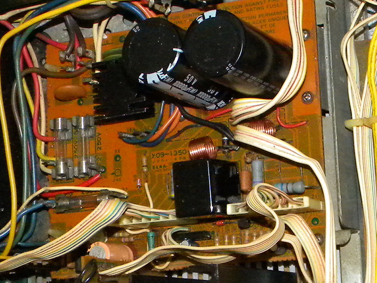
So, I just found out that the transformer in this thing is outputting 70V instead of 34V and I do not know what would be the cause of this nor how this would happen. I do know that transformers output a but more than their ratings when not under load but I doubt that margin would be over 10V max. All the transformer connections look original and the only thing I have changed are the power transistors. Please help me or I am going to absolutely lose my mind. (And yes the amplifier is connected to 125 because it’s from America)
 
Register to hide this ad
Where/how are you measuring the voltage? If measuring Pins 27 and 28 you'll get about 68VAC. If measuring Pins 27 OR 28 AND 26 you should have 34VAC.

Craig
 
Last edited:
As was asked above, exactly what points are you taking the measurements from?
 
Last edited:
See post #2. A to C is across pins 27 & 28. That is the correct voltage on those pins.
 
See post #2. A to C is across pins 27 & 28. That is the correct voltage on those pins.
Ah, I have just measured pins 26 and 28 but now I’m seeing 15,6 volts. Also, measuring the voltage going into the power amp section, I see -70 instead of -46
 
Pins 26 to 28 should be half of the 70vac you showed in post #1. Pins 26 to 27 should also be half of the 70vac you measured in post #1. If you're getting -70vdc instead of -46vdc I'd check the rectifier to see if it's bad.
 
I would like to see the voltage measurements with the meter negative lead connected to Pins 26/29 on the X09-1350-10 power supply board. The DC voltage measurements from the ± connections of both of the 10,000µF main filter capacitors would be informative.
 
Pins 26 to 28 should be half of the 70vac you showed in post #1. Pins 26 to 27 should also be half of the 70vac you measured in post #1. If you're getting -70vdc instead of -46vdc I'd check the rectifier to see if it's bad.
I am getting 18Vac between pins 26 and 27/28
 
I would like to see the voltage measurements with the meter negative lead connected to Pins 26/29 on the X09-1350-10 power supply board. The DC voltage measurements from the ± connections of both of the 10,000µF main filter capacitors would be informative.
Will test when I’m back home
 
I also replaced the burnt put relay and it isn’t clicking in even after 1 minute of waiting suggesting either a faulty relay IC or low voltage (as I measured)
 
18VAC from Pin 26 to 27 and also from Pin 26 to 28 is too low. Is the unit connected through a dim bulb tester?

Is this a multi-voltage unit, with 100/120/220/240 input?
 
18VAC from Pin 26 to 27 and also from Pin 26 to 28 is too low. Is the unit connected through a dim bulb tester?

Is this a multi-voltage unit, with 100/120/220/240 input?
No it’s not connected to a dim bulb tester nor is it a multi voltage unit. It’s for 120 and it is connected to 125. Interestingly from pins 27 to 28 it is fine but not from pins 26 to 27/28
 
It would appear that the center tap (ground) connection at Pins 26 and 29 are suspicious.

KenwoodKR-6050IPowerSupply.jpg


The wires are wrapped on pins, and could have marginal connections.
 
in my case they aren't wrapped around the pins but directly soldered on, I guess the tech that has been here before thought it was a good idea to solder these wires on so it can't be a bad connection
It would appear that the center tap (ground) connection at Pins 26 and 29 are suspicious.

KenwoodKR-6050IPowerSupply.jpg


The wires are wrapped on pins, and could have marginal connections.
 
Back
Top Bottom