• The move to the new server is done. There are some software and database maintenance updates in process. This has us passing the hat around to help out. We appreciate any donations. Seriously, even a dollar helps. The payment page may be found here - https://www.audiokarma.org/support.html

Kenwood amp KS-4000R - what part am I?

oldNslo

Active Member
Yup, she's old. Not been fired up in 10 years, but its a family (ahem), component. I've pulled it from a very dark shed, and she's passed the dim bulb tester, and sets the front panel lights aglow.

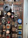
I've pulled it from the (almost) wood case, and upon a good dusting with the air hose, saw this circular trinket jiggle below the unknown circuit board part. VR7, of which I cant find a service manual anywhere.

What is this metal part (referenced by the toothpick)? What does it control?

As of yet, I've not tried to hook speakers up. Those crusty RCA terminals are being cleaned today and hopefully a whopping 14 watts of window shaking sound will erupt.
IMG_6610.JPG
 

Attachments

  • IMG_6612.JPG
    IMG_6612.JPG
    100.5 KB · Views: 19
Register to hide this ad
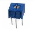
Here's a screenshot of it. It's a trim pot to set bias.

Can't find a service manual so I can't tell you any more.
If you replace it with another 1kΩ trim pot set it to minimum resistance. See what the other channel has for bias then set this one the same.

Measure the good channel across the output emitter resistor then do the same for the other channel and adjust the new trim pot to the same mv.

Be careful and use mini grabbers so you don't short anything.

Screenshot (830).jpg

Screenshot (829).jpg
 
Last edited:
The trim pot that looks like VR7 for the other channel is VR6. It should be easy to find.
I'd get two Bourns trim pots, adjust them to minimum resistance.
Measure the bias on the good channel first so you know what it is, then replace both of them and set bias accordingly.

New trim pots won't look like those.
Screenshot (832).jpg
 
Ok, thanks all. I have my work cut out for me, being new to diagnostics, and somewhat green to circuit board repair. I spent the past few days de-soldering components from scrap circuit boards (for practice and fun), the next step will be to understand bias, and the resulting setting. Using this as a reference: How do YOU set bias?
 
This morning the amp got speakers and an antenna attached. Holy smokes, there was stereo sound, and all the functions work (tho a bit scratchy). It's been playing for an hour. Agreed @kwayde on the numbering system for the other side, and while all other components share a similar numbering system on the flip side, VR6 (or anything) just does not exist on the board. I'll press on and remove the board, order parts and install.

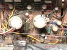
Here's the before pic. Yeah...yuk. :oops:

For me, this is a training project, and I enjoy learning and the experience gained.
IMG_6103.JPG
 
It's been a minute, since I have gotten to this, and with the past weeks temps of 110d or higher, its indoor projects for awhile. :)

I'm at the point where I need to measure Bias for the trim pots (the one good one) noted in the above posts. I'll presume the left side of the CB (from above) is the left speaker.

Q1 - So am I correct that the transistors needed for measuring bias are noted with the red arrows? (see pic)Back.JPG

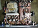
Bias trim pot locations below and shot of the forward section of the board.

Front.JPG I need to test are
Q2 - I don't see trim pots for the OFFSET adjustment, perhaps this does not have an adjustment? I watched a YT with a Sansui that had very similar circuitry and those offset trim pots were very visible and discussed.

Top shot.JPG

See my pic of the overhead shot above, to confirm I am not missing the OFFSET trim pots location.

Thanks!
 
Yup, she's old. Not been fired up in 10 years, but its a family (ahem), component. I've pulled it from a very dark shed, and she's passed the dim bulb tester, and sets the front panel lights aglow.

I've pulled it from the (almost) wood case, and upon a good dusting with the air hose, saw this circular trinket jiggle below the unknown circuit board part. VR7, of which I cant find a service manual anywhere.

What is this metal part (referenced by the toothpick)? What does it control?

As of yet, I've not tried to hook speakers up. Those crusty RCA terminals are being cleaned today and hopefully a whopping 14 watts of window shaking sound will erupt.
View attachment 3674871
It looks like a trimmer potentiometer with the wiper assembly missing. The 'VR' designator means variable resistor. If all three leads are employed in the circuit, then it as acting as a potentiometer. If only two of the three leads are connected, then it is acting as a variable resistor.
 
Back
Top Bottom