

You are using an out of date browser. It may not display this or other websites correctly.
You should upgrade or use an alternative browser.
You should upgrade or use an alternative browser.
Kenwood Basic M1 Power Amplifier Restoraton/Upgrade
- Thread starter Leestereo
- Start date

How do you like those Maggies?
thanks. by far my nicest speakers i've owned. I'm always looking for good sounding gear on a budget and these fit perfectly. I keep my monoblocks behind each Maggie. I'd like to think the amp weight on the stands keep the speakers planted.
Hi all,
I took at a turn with my recently-acquired M1.
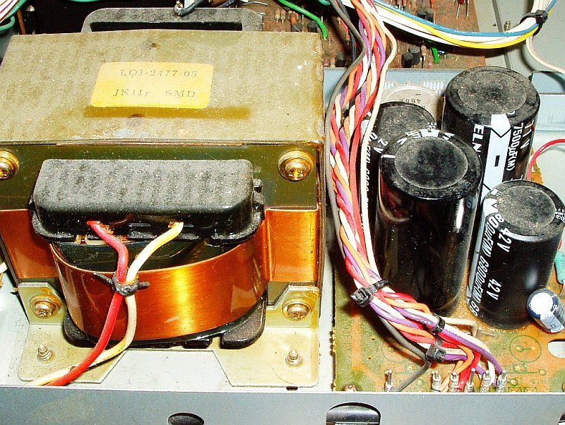
I've only replaced the low-voltage filter capacitors so far since I CANNOT find something that will physically fit the high voltage rail side. Typically I buy from Mouser. Any tips?
View attachment 2053515
Here's the full board:
View attachment 2053517
I applied the current source mod:
View attachment 2053514
The casualties:
View attachment 2053516
I don't think Dan Mattis has output connector kits for the M1 like he does for the M2 and M2A. I might try to create replacements of my own to replace the stock, substandard speaker cable connectors. I need proper banana or spade connectors.
Hi,
I think Leestereo mentionned 35mm diameter capacitors can fit in for the power supply board. I purchased a pair of Mundorf 10000µF for my m1, and a pair of Nichicon FW capacitors in 20mm, 10000µF 50V.but did not try yet to fit them as I toasted the left channel during the final idle current setting after mainboard upgrade...
 . I'll create a dedicated post as I need some help to troubleshoot!
Enjoy your nice restauration.
Last edited:
Craig.Coffer
New Member
I know this might seem like a daft question to some of you out there, but I was wondering whether I could change these resistors (see quote below) in the Basic M1 circuit from 18 Ohms to 15 Ohms ... They are the resistors to which ceramic capacitors have been soldered. The reason for asking is that I have 15 Ohm tantalum resistors that I would like to use is the signal path and before ordering 18 Ohm resistors I thought that 3 Ohms might not make such a difference in this circuit... By the way I am not electronics technician. I am self taught and obviously lack some of the technical specifics...
Thanks for any comments from the technical experts who know this circuit (easily available on the web).
Cheers...
Thanks for any comments from the technical experts who know this circuit (easily available on the web).
Cheers...
Hi
I noticed on the last picture that you changed the resistors R100 (R99?), R94 (R93?). What was the reason for the change? What kind of resistance and capacitor values have followed?
PS
good job:thmbsp:!!!
Andy

ajfink
Member
I know this might seem like a daft question to some of you out there, but I was wondering whether I could change these resistors (see quote below) in the Basic M1 circuit from 18 Ohms to 15 Ohms ... They are the resistors to which ceramic capacitors have been soldered. The reason for asking is that I have 15 Ohm tantalum resistors that I would like to use is the signal path and before ordering 18 Ohm resistors I thought that 3 Ohms might not make such a difference in this circuit... By the way I am not electronics technician. I am self taught and obviously lack some of the technical specifics...
Thanks for any comments from the technical experts who know this circuit (easily available on the web).
Cheers...
I figured someone else would jump in, sorry for the late response.
Yes, you CAN, assuming they are of the same or higher power rating. That said, resistors are cheap, and dropping the resistance will increase the voltage passed through down the line. I'd spend a few bucks to get what the doctor ordered.
Craig.Coffer
New Member
I figured someone else would jump in, sorry for the late response.
Yes, you CAN, assuming they are of the same or higher power rating. That said, resistors are cheap, and dropping the resistance will increase the voltage passed through down the line. I'd spend a few bucks to get what the doctor ordered.
Thanks a lot for your reply... and yes I did what the doctor ordered to be on the safe side ... and put in 18 Ohm tantalum resistors with polystyrene caps ... and it sounds great!
ajfink
Member
Thanks a lot for your reply... and yes I did what the doctor ordered to be on the safe side ... and put in 18 Ohm tantalum resistors with polystyrene caps ... and it sounds great!
Good, I'm glad. What I didn't include in my previous post is that I personally wouldn't have used the 15 Ohm resistors in this case. More likely to reduce lifespan of or outright burn out components by using lower value resistors where higher ones are called for.
AK member Unican Eric brought in this Kenwood M1 for a complete restoration and upgrade. The M1 is a well regarded 105 wpc power amplifier from Kenwood's Basic series and definitely merits a restoration/upgrade. The restoration/upgrade plan for this Kenwood M1 consists of the following:
1. Replace all of the power supply electrolytic capacitors with higher spec. 105°C low ESR types (increasing capacity where appropriate and possible).
2. Implementation of the DRM Audio Kits' current source modification.
3. Installation of emitter degeneration resistors for the input differential pair.
4. Replace the signal path capacitors, with either film types or C0G/NPO types, as appropriate.
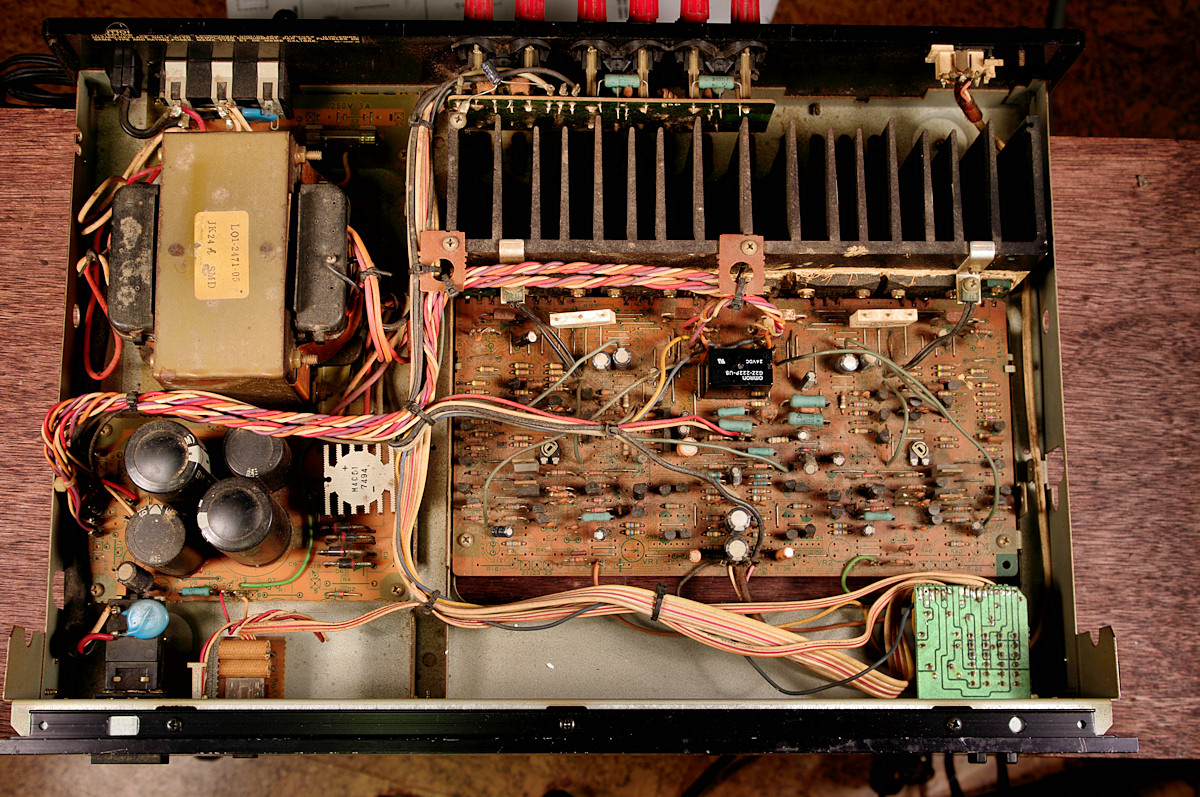
Here are some pictures of the Kenwood Basic M1 power amplifier as first received:


I have recently resurrected a dead M1 and have a question about setting the bias. The manual calls for a bias of 8-20mv across R113 (R114). Since this is a compound resistor with a total of .22 ohms in series with .22 ohms, should the measurement be across the entire resistor (.44 ohms) or only half?

PabloTincho
Super Member
Do you guys know the difference between M1 and the M1A ?

PabloTincho
Super Member
what about the sigma drive ?
is you see a few pic, the 1M seems better, more circuits ?
M1
M1A
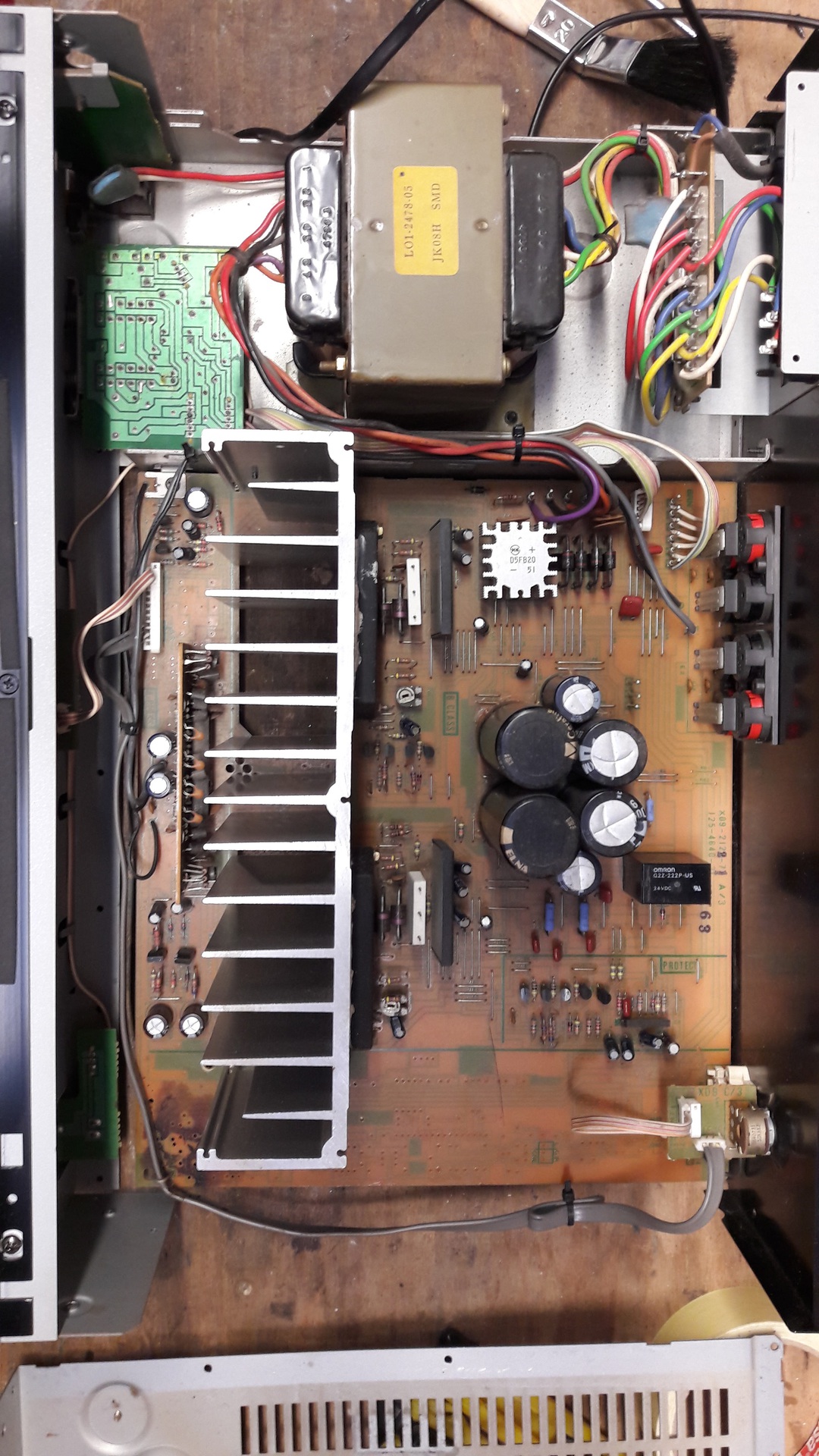
which one is better ?
is you see a few pic, the 1M seems better, more circuits ?
M1
M1A
which one is better ?
Last edited:


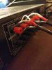
I made my own. Pic to follow. I paralleled 18ga wire with 14ga. At the speaker end they combine and are just one wire into the terminals. At the amp end they remain separate to hook up as appropriate. Can't say I really hear a difference, but since I went to the trouble of making them, I use them.to use sigma drive you need special cable with 4 wire cable

Last edited:
Sigma Drive is just an extra feedback loop from the speakers. Reputed to improve bass and raise the damping factor, but who knows. I didn't hear a huge difference with my KA-900. With careless handling, it's a good way to fry the outputs though.....
I'm curious as to why these amps have a "BPC" reputation though -- I have a KM-106, and the schematic looks very very close the that of any of the rest of the well regarded integrated amps of the period. No massive filter caps of course (and they aren't needed really) and sure, they won't drive a dead short pretending to be a speaker, but they should be very clean, powerful amps. Think it might be because they aren't "exclusive" or "audiophile" limited editions?
Haven't fired mine up yet (have to locate a remote for the pre-amp so I can use the external volume control) but I expect it to sound very much like my KR-950 or KA-900, which is to say very good.
I'm curious as to why these amps have a "BPC" reputation though -- I have a KM-106, and the schematic looks very very close the that of any of the rest of the well regarded integrated amps of the period. No massive filter caps of course (and they aren't needed really) and sure, they won't drive a dead short pretending to be a speaker, but they should be very clean, powerful amps. Think it might be because they aren't "exclusive" or "audiophile" limited editions?
Haven't fired mine up yet (have to locate a remote for the pre-amp so I can use the external volume control) but I expect it to sound very much like my KR-950 or KA-900, which is to say very good.

BilboBaggins
Addicted Member
I had the KA-1000, and I didn't like it much. I think I traded it to my tech for labour. I tried it both ways. I didn't hear a difference. I think the reason it gets the BPC categorization, is if you pick up the amplifier section, it feels way too light. Of course, because the power supply is where all the heavy parts are! Which is quite heavy. It also takes more space. But I didn't find mine sounding all that great. For $100 though, it is quite a bit of amp, if all is working.Just my two cents.
I certainly do not notice a lack of bass with my -900, but them I'm driving HPM 900's with it. I've found Kenwoods to be very linear (and a KA-52 will drive HPM-500's down to 15Hz, I couldn't hear 10Hz). That may be the problem, they aren't bass heavy.
An efficient design doesn't depend on a huge transformer to supply proper bass after all.
An efficient design doesn't depend on a huge transformer to supply proper bass after all.