• The move to the new server is done. There are some software and database maintenance updates in process. This has us passing the hat around to help out. We appreciate any donations. Seriously, even a dollar helps. The payment page may be found here - https://www.audiokarma.org/support.html

Kenwood Basic M1 Power Amplifier Restoraton/Upgrade

Thanks for stopping me from creating a major short circuit!!!
I made the dim bulb tester!
When I turn it on, the bulb lights up, then dims until it remains very dim.
After a few seconds, I hear the relay unlock and then immediately go into safety mode.
I'm testing!
In any case, this dim bulb tester is very safe!
 
The amplifier was working fine before the upgrade, with voltages at R113 and R114 already at 0V. I was never able to measure the previous bias values.

After completing the repair and fixing my mistakes — including an accidental short circuit during the process — the situation remains the same: no measurable bias voltage : 0 mV

I placed the multimeter probes on the outer legs of R113 and R114 and adjusted the bias trimmers with a screwdriver up to the 12 o’clock position, but the voltage still reads 0mV.

Any advice on how to proceed or what I might be missing?
 
Additionally, I tested the middle legs of R113 and R114 against ground and measured approximately -3 V on both sides. The outer legs of R113 and R114 show good continuity between each other…
 
Additionally, I tested the middle legs of R113 and R114 against ground and measured approximately -3 V on both sides. The outer legs of R113 and R114 show good continuity between each other…
I'm pretty sure the center pin of R113 to ground should be 0v (and R114).

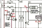
You could measure pin 1 and 2 of IC1 and post results. They both should be 0v too.

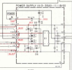
My schematic isn't the best:

1750263710667.png

the input to R132 and R131 should also be 0V.

if not 0V on any of these measurements should narrow down the problem.
 
Thanks for your help !
Here's my measurements !
IC1 pin 1 : 3,6 mV
pin2 : -154,6 mV
R131 : -155,5 mV on one leg and -3,12 V the other
R132 : -153,5 mV and -3,10 V
 
It will stay in protection with 3V on the outputs!

Check the rail voltages at the main filter caps, I've seen a main filter cap blown out by a shorted output. they will be low due to the DBT, but should be equally distant from 0V..

Also, have you checked the current limiter transistors? I couldn't set the bias on a KA-87 with a very very similar circuit until I replaced all of them. When shorted then will ground the input signal, resulting in no current flow through the outputs.
 
It will stay in protection with 3V on the outputs!

Check the rail voltages at the main filter caps, I've seen a main filter cap blown out by a shorted output. they will be low due to the DBT, but should be equally distant from 0V..
you could just post the values listed below in red. hopefully close
1750301781289.png
 
OK. i made measurements ! hope it's easy to understand for you (not really for me but it seems I need to change some things)
C8 +52,30V
C7 -47,96 V

For the red values (if I'm right on how to measure it))
R51 one leg -77V / the other from -100 to -77
R52 -78V / -78,3
R53 -77,9V / the other from -100 to -77
R54 -78V
Q25 (C2591): B–C: 0.6 V / B–E: 1.9 V / C–E: 0.580 V / E–C: 0.580 V
Q26 (C2591): B–C: 0.550 V / B–E: rising from 1.7 V up to OL / C–E: 0.6 V / E–C: 0.6 V
Q27 (A1111): B–C: 0.5 V / B–E: 0.5 V / C–E: 0.6 V / E–C: 1.9 V
Q28 (A1111): B–C: 0.6 V / B–E: 0.7 V / C–E: 0.5 V / E–C: OL (rising)

Q15: B–C: 0.888 V / B–E: 1.086 V / C–E: 0.6 V /E–C: 0 V
Q16 : B–C (0,6 V) / B–E (0,6 V) / C–E (0,8 V) / E–C (OL)
Q17 : B–C (0,6 V) / B–E (0,6 V) / C–E (0,8 V) /E–C (OL)
Q18 : B–C (0,9 V) / B–E (0,9 V) / C–E (0,6 V) / E–C (OL)

Q21 : B–C (0,6 V) / B–E (1,28 V) / C–E (1,5 V) / E–C (1,19 V) rising
`Q22 : B–C (1,5 V) / B–E (1,6 V) / C–E (0,6 V) / E–C (0,6 V)
Q23 : B–C (1 V) / B–E (0,5 V) / C–E (0,7 V) / E–C (1,23 V rising)
Q24 : B–C (0,7 V) / B–E (0,6 V) / C–E (1 V) / E–C (1,25 V rising)

I think I have to change all Q25 to 28 and some other transistors (all of them ?? ) like HPMguy suggested)

thank you again for your help !

 
OK. i made measurements ! hope it's easy to understand for you (not really for me but it seems I need to change some things)
C8 +52,30V
C7 -47,96 V

For the red values (if I'm right on how to measure it))
R51 one leg -77V / the other from -100 to -77
R52 -78V / -78,3
R53 -77,9V / the other from -100 to -77
R54 -78V
Q25 (C2591): B–C: 0.6 V / B–E: 1.9 V / C–E: 0.580 V / E–C: 0.580 V
Q26 (C2591): B–C: 0.550 V / B–E: rising from 1.7 V up to OL / C–E: 0.6 V / E–C: 0.6 V
Q27 (A1111): B–C: 0.5 V / B–E: 0.5 V / C–E: 0.6 V / E–C: 1.9 V
Q28 (A1111): B–C: 0.6 V / B–E: 0.7 V / C–E: 0.5 V / E–C: OL (rising)

Q15: B–C: 0.888 V / B–E: 1.086 V / C–E: 0.6 V /E–C: 0 V
Q16 : B–C (0,6 V) / B–E (0,6 V) / C–E (0,8 V) / E–C (OL)
Q17 : B–C (0,6 V) / B–E (0,6 V) / C–E (0,8 V) /E–C (OL)
Q18 : B–C (0,9 V) / B–E (0,9 V) / C–E (0,6 V) / E–C (OL)

Q21 : B–C (0,6 V) / B–E (1,28 V) / C–E (1,5 V) / E–C (1,19 V) rising
`Q22 : B–C (1,5 V) / B–E (1,6 V) / C–E (0,6 V) / E–C (0,6 V)
Q23 : B–C (1 V) / B–E (0,5 V) / C–E (0,7 V) / E–C (1,23 V rising)
Q24 : B–C (0,7 V) / B–E (0,6 V) / C–E (1 V) / E–C (1,25 V rising)

I think I have to change all Q25 to 28 and some other transistors (all of them ?? ) like HPMguy suggested)

thank you again for your help !
Sorry for my long long text !!
 
Not the thread police here, but it REALLY would have been better for @valimar to start his own thread regarding the issues he's having, vs adding onto Leestereo's excellent upgrade thread.
 
Hello! I'm wondering how many of these upgrades are applicable to the Basic M1A. Considering the age of the thing and it's proprietary transistor modules I'd like a recap for peace of mind even though its working great as is. There's very little information online as to restoration of the M1A and figured it would be a good idea to ask Lee since I performed his C1 restoration with great results in the past.
 
Back
Top Bottom