

You are using an out of date browser. It may not display this or other websites correctly.
You should upgrade or use an alternative browser.
You should upgrade or use an alternative browser.
Kenwood KA-5500 catastrophe - please help
- Thread starter mccaffrp
- Start date
-
- Tags
- kenwood ka-5500

Qe23,24 - MJ21194G
Qe35,26 - MJ21192G
i hope that was a typographical error. The complimentary device for the MJ21194G is the MJ21193G. In some instances, the MJ21194G/21195G are used as complimentary pairs, but that MJ21192 is hopefully wrong.

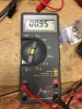
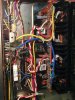
Yes, that was a typo. 93 and 94's are installed. I put in a 100 Watt bulb and still the amp does not turn on. So I put my meter on the current draw in AC mode and I am getting .9A draw but steady. See attached.
Attachments

It appears that the outputs are socketed. If so, you might pull the outputs on the questionable channel and try your 60W in the DBT again. Apparently, the outputs are not grounded, but in case something is biasing them on hard, this will potentially indicate that.
I double checked the driver polarities, I had a photo of the originals as well as the board is marked. I checked the NTE parts against the originals' datasheet and polarity is the same. I checked for cold solder joints, checked the input differential polarities, also marked on board, I removed VR2 and R26,R28, checked those ( no problems) but I replaced R26,R28 anyway and reinstalled VR2. I reinstalled the outputs and tested again and same issue. Not powering up. How and where do I trace next? Should I remove the outputs again and turn back on and test voltages? if so, where first?
Ok, no replies for a bunch of hours, I understand "tough love" ! Well, I forgot to check TH2, so I compared it to the other one, and....no go. It was not open. So then I just sat and read the schematic and imagined what might be taken out next by my stupid move of a few weeks ago. I spent more time checking resistance measurements and comparing it to the other channel, I found that a few measurements of resistors in the bias string mentioned above were lower than they should be. The most noticeable offender was a partial short across R 24 that measures 1.2K instead of 3.9K. I traced the issue to Q 10 - when I removed Q 10 and measured R24 again, it measured proper. So I subbed Q10 with a spare KSA992 and everything powered up and works properly now. Its strange that Kenwood has the 2SA620 listed for Q10 but the part actually installed was a 2SA721. Thanks to everyone for your help (and your lack of help because it forced me to dig deeper myself!) Now on to setting bias again...the correct way!
The "tough love" theory is interesting, but not valid in this instance. Your thread wasn't intentionally being ignored (at least not by me) but life gets in the way. Good job on tracking down the problem. After eliminating the outputs and drivers themselves, there wasn't much left but the upstream devices/circuits biasing those drivers at the wrong levels for any of a multitude of reasons. You're fortunate that the thermal compensation was intact, since those can be tough to source.
Interestingly, a lot of those 2SA7xx devices seem to have various problems. Perhaps this is another variant to add to the list of problem devices.
Interestingly, a lot of those 2SA7xx devices seem to have various problems. Perhaps this is another variant to add to the list of problem devices.

I traced the issue to Q 10 - when I removed Q 10...Thanks to everyone for your help (and your lack of help because it forced me to dig deeper myself!) Now on to setting bias again...the correct way!
When I fixed a marantz 250, I think all the transistors where blown not just the outputs and drivers. I had to test them all. BTW, if you want to see lack of help, check my post over on the Marantz forum. We all get busy with our own projects (want a SAE amp? I'm about ready to throw it down the street).
I still think it is great documenting the fix for the next guy.
Thanks again guys, of course I was just kidding about the "tough love" comment and it was only based on the fact that Mr. Watthour was responding quite quickly earlier in the day and then no one else had responded for many hours. I understand completely the processes in play here, I wanted to learn from my mistakes without "shotgunning". Of course I understand life gets in the way, I am still working for a living, and this is just a hobby for me, its been more than 40 years since my electronics training and I've forgotten lots of it. So I appreciate the help yesterday Mr. Watthour! With the help here, I determined that something was biasing the newly replaced outputs strongly and I am really glad I had a working channel to compare static component readings to and at least I didnt have to remove every part to finally arrive at the culprit. I'm also glad I could sub Q10 with something I actually had in stock. The only thing that is different about the newly repaired channel is that it now shows 30mV on the DC offset and the orignal channel shows 15mV. This is after adjusting the bias on both channels. I did replace all 4 input differentials. Now I have not replaced any caps yet because the amp is dead silent and sounds great. But I am wondering if using that A992 in place of the A721 is what is causing the slight difference. I'd like to get the repaired (right) channel to match the original if it doesnt take too much more component replacement.
We're talking millivolts, and a very slight difference in resistor tolerance between the two channels and both halves of a specific channel will affect that. Ideally, the circuit could be modified upstream to add bias adjustment, but that would be an undertakling in a unit where that provision did not already exist. Resistance back in the differential area (R56) going to be a controlling factor.