Gronard
New Member
Hi,
I have just bought my first vintage Kenwood amplifier: KA 8004
The amp seems to be working fine and sounds good but when I tried to check and adjust the bias setting according to manual I am getting really strange values.
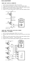
According to the service manual the bias should be set to 20mV by adjusting Vre1 (measure on terminal 2 and 4) and Vre2 (measure at terminal 1 and 3).
Measuring at 2 and 4 gives a low voltage about 5mV (unstable) adjusting Vre1 does not change anything.
When measuring at 1 and 3 I measure 36V :-( adjusting Vre2 does not change anything.
When I measure at the speaker terminals I get the same results.
Any ideas on what could be wrong?
Thanks,
Bernard
I have just bought my first vintage Kenwood amplifier: KA 8004
The amp seems to be working fine and sounds good but when I tried to check and adjust the bias setting according to manual I am getting really strange values.
According to the service manual the bias should be set to 20mV by adjusting Vre1 (measure on terminal 2 and 4) and Vre2 (measure at terminal 1 and 3).
Measuring at 2 and 4 gives a low voltage about 5mV (unstable) adjusting Vre1 does not change anything.
When measuring at 1 and 3 I measure 36V :-( adjusting Vre2 does not change anything.
When I measure at the speaker terminals I get the same results.
Any ideas on what could be wrong?
Thanks,
Bernard
Last edited: