• The move to the new server is done. There are some software and database maintenance updates in process. This has us passing the hat around to help out. We appreciate any donations. Seriously, even a dollar helps. The payment page may be found here - https://www.audiokarma.org/support.html

Kenwood KR-3130

Randy007

Well-Known Member
Hello AK friends, I need help setting the bias on my Kenwood KR-3130...I have got the right channel working by replacing the output transistors and drivers..However, I have distortion on the right channel and the output is low....any help would be greatly appreciated..thanks
 
Register to hide this ad
I have read both threads and I'm more confused than before, I'm not stupid....I have adjusted bias on a few receivers but this one is different. if you can't or don't have the time to help me just say so. I'll try something else....I'm not an experienced tech, I do need help just like all the other folks on hear from time to time....sorry about the rant!!!
according to this I should be measureing pin pin 42 and 48 for KR-3130 correct? and pin 41 and 47 correct?
 
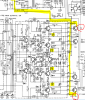
If you look at the schematic, to the right of Pin 37 it says 20ma, so that's your target current for the output stages. Now follow Pin 37 out thru the Q1 and back into Pin 41 thru Re91 back out Pin 45 thru Q2 back in Pin 47 and thru Re93 and finally to ground. When setting the bias or idle current you are setting the current thru the entire circuit we just went thru. Now for some math, E/I x R is the formula we want use in this case where E = Voltage, I = current and R = resistance. We have two known numbers current, 20ma, and we have the resistance, .47 Ohms. So using the formula we have to solve for E or Voltage. .020 x .47 = .0094 or 9.4mv. So on Pins 47 and 49 we want 9.4mv. Same as on Pins 48 and 49. The same voltage could also be read on Pins 41 and 45 and also on Pins 42 and 46. Clear as mud now.

I don't think setting the correct bias will fix your low output problem or any major distortion problem.. If it doesn't start comparing voltages on the all of the transistors with the good channel.

Craig

 
If you look at the schematic, to the right of Pin 37 it says 20ma, so that's your target current for the output stages. Now follow Pin 37 out thru the Q1 and back into Pin 41 thru Re91 back out Pin 45 thru Q2 back in Pin 47 and thru Re93 and finally to ground. When setting the bias or idle current you are setting the current thru the entire circuit we just went thru. Now for some math, E/I x R is the formula we want use in this case where E = Voltage, I = current and R = resistance. We have two known numbers current, 20ma, and we have the resistance, .47 Ohms. So using the formula we have to solve for E or Voltage. .020 x .47 = .0094 or 9.4mv. So on Pins 47 and 49 we want 9.4mv. Same as on Pins 48 and 49. The same voltage could also be read on Pins 41 and 45 and also on Pins 42 and 46. Clear as mud now.

I don't think setting the correct bias will fix your low output problem or any major distortion problem.. If it doesn't start comparing voltages on the all of the transistors with the good channel.

Craig
Thanks Craig, will keep you informed...thanks again
 
randy, here is a schematic markup similar to the one i posted in your other thread. i highlighted the emitter resistors.q1-q4-voltages-emitters.PNG
 
randy, here is a schematic markup similar to the one i posted in your other thread. i highlighted the emitter resistors.View attachment 1697005
Rickl, thanks I have the schematic...I see the flow, when I connecct my DMM to pin 42 and 49 I'm reading 28.30V....this should be the right channel ?...on the other side Pins 41 and 49, I'm reading 22.39V...Am I measuring wrong? I should be reading a low voltage correct, like 9.4mV.?
 
Left channel bias is between 41 and 45, or between 47 and 49 (49 is ground). Right is between 42 and46, or between 48 and 49 . Either point should be the same, if not, then probably out of spec emitter resistors. when you are going from 41 or 42 to 49, you are looking at the center voltage plus the bias. Schematic indicates 23.5 volts for center voltage, so I suspect the 28.3 voltage is in bad channel. If semiconductors test ok, check resistors. Voltages around QE12 should indicate directions to look.
 
Left channel bias is between 41 and 45, or between 47 and 49 (49 is ground). Right is between 42 and46, or between 48 and 49 . Either point should be the same, if not, then probably out of spec emitter resistors. when you are going from 41 or 42 to 49, you are looking at the center voltage plus the bias. Schematic indicates 23.5 volts for center voltage, so I suspect the 28.3 voltage is in bad channel. If semiconductors test ok, check resistors. Voltages around QE12 should indicate directions to look.
Thanks Steve appreciate you responding...on
Pin 41 and Pin 45 I'm reading 0V
Pin47 and 49 reading 0V
this is the left channel...

Pins 42 and 46 reading 27.5V
Pins 48 and 49 reading 8mV
this is the right channel...correct?
on Qe12 Emitter 2V, should be .3V same as Qe11...correct?
 
Pins 42 and 46 reading 27.5V
Pins 48 and 49 reading 8mV
this is the right channel...correct?
on Qe12 Emitter 2V, should be .3V same as Qe11...correct?
42 to 46 should be the same as 48 to 49. 8 mV would be normal. 27 volts says emitter resistor is open (looks like Re92. One of the block 0.47 ohm resistors. This might also account for the high voltage at the emitter of Qe12. Because of feedback, anything wrong somewhere upsets the voltages everywhere. Also check the resistor at the emitter of Qe12.
edit - or you could be measuring on wrong pin... :)
 
42 to 46 should be the same as 48 to 49. 8 mV would be normal. 27 volts says emitter resistor is open (looks like Re92. One of the block 0.47 ohm resistors. This might also account for the high voltage at the emitter of Qe12. Because of feedback, anything wrong somewhere upsets the voltages everywhere. Also check the resistor at the emitter of Qe12.
edit - or you could be measuring on wrong pin... :)
Qe12 emitter resistor Re78 measures 99.5 ohms is good, Re92 measures .7 ohms...
 
Steve I apologize, Pin42 and 46 are reading 0V...you were right I had the wrong pins.
Steve I just adjusted the voltage on 42 and 46 to 8mV and I have the all clear, no distortion ojn either channel....could this have been what was causing the distortion, trying to adjust voltage at the wrong pins? wait I spoke to soon, I have no distortion listening through a pair of headphones, but when I hook up to speakers, I have distortion in right channel....any ideas?
 
Headphones draw nearly no current so the drivers, Qe14/16, are able to handle the load of the headphones. It appears your output stage has a problem. Check the voltage across Pins 48 and 49, should be the same or nearly the same as Pins 42 and 46. I don't suppose you have a signal generator and o'scope would you?

Craig
 
Headphones draw nearly no current so the drivers, Qe14/16, are able to handle the load of the headphones. It appears your output stage has a problem. Check the voltage across Pins 48 and 49, should be the same or nearly the same as Pins 42 and 46. I don't suppose you have a signal generator and o'scope would you?

Craig
Thanks Craig, I do not have a signal generator, but I do have an oscope.. I'm reading 11mV on pins 48 and 49, and 0V on Pins 42 and 46. Yesterday I repla ced a transistor Q10 with a KSC1845 and now the right channel doesn't work at all...:beerchug:
 
2SC458 and 2SC1345 get people confused all the damn time because the part ID is on the back with the outhouse to-92 package. This photo really needs to be a sticky.
9tULFjd.jpg
 
Back
Top Bottom