• The move to the new server is done. There are some software and database maintenance updates in process. This has us passing the hat around to help out. We appreciate any donations. Seriously, even a dollar helps. The payment page may be found here - https://www.audiokarma.org/support.html

Kenwood KR-6200 FM IF Sweep Question

Richard P

Now Many Reel to Reels is Too Many
Subscriber
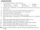
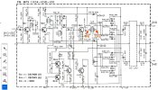
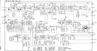
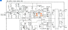
Quick Alignment question on a Kenwood KR-6200. The SM has me injecting the sweep signal at TP1 and pulling the signal at TP2, adjusting La7 and Lb1 for best IF waveform. This doesn't really make any sense since TP2 pulls the signal before it gets to Lb1 and on my board, all of the components associated with TP2 are not installed (red X's on the photo). It seems to me that I should be pulling the IF signal from point 'A' to adjust La7 and point 'B' to adjust Lb1 or just point 'B' to adjust both. Any thoughts?

The rest of the alignment instructions are equally nebulous but I think I can muddle my way through . . .
1705941847920.png

Capture2.JPG
 
Register to hide this ad
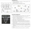
Quick update and new question on this alignment process. I was able to get the IF sweep alignment done using point A indicated above to tune La7 and I pulled the signal off the collector of Qb4 or Qb5 (I don't recall which one I ended up using). IF waveforms had flat tops initially, but I attenuated the input signal down a bit to get a form closer to what is shown in the manual ( i'm using a Heathkit IG-57A sweep generator). Discriminator distortion was measured and minimized using REW software and a FocusRite Scarlett 2i2 audio interface. That seemed to work really well. The rest of the alignment went pretty well, although the procedure is not very clear.

The MPX section is where I ran into my next roadblock. I was able to peak the output (step 3) for Lc2 & Lc3 but Lc4 had no effect. For the rest of the steps, Lc4 still had no effect, VRc2 would not turn the stereo light on and I can't adjust separation using VRc1. FM sounds really clear, but I'm not getting a stereo signal and the stereo light doesn't come on until i tune slightly off station.

Any thoughts? I'm wondering if Lc4 is open or the LPF is causing issues.


CaptureC.JPG

CaptureA.JPG

CaptureB.JPG
 
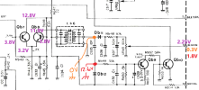
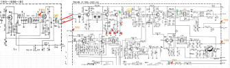
Looking through a thread that @Ylli was helping on for a KR-5200 with same IF & MPX boards, I've discovered that the gate signal on pin 8 of the MPX board stays high when switching from no signal to a strong stereo signal --> 2.25V strong signal, 2.0V weak signal. That would steer me back to the IF board and circuit feeding pin 10 (pin 8 on the MPX board)

Some odd findings:

- Voltages shown in purple are for a strong stereo signal
- When I measure voltage at the orange point, I read 0VDC (probably an AC signal) but the voltage on pin 10 drops to 0.3V
- when I measure voltage at the red point, I read 12.6V but the voltage on pin 10 drops to 1.8V
- How does a 10 Mohm DMM affect the voltage on pin 10 when probing the circuit??


tempsnip1.png
 
OK. Solved my own problem. I went back through the alignment to make sure I didn't miss anything and rechecked all the transistors and diodes on both boards - all tested good with a DMM/Diode test. I started checking voltages, although there aren't too many listed on the schematic and they seemed reasonable except for Q2 and Q3 on the MPX board were a little high or low. It wasn't until i figured out that the voltage reading shown in boxes on the schematic are actually AC voltages that the problem jumped out. In input was right around 150mVAC but the others were all over the place. Replaced Q1 - Q3 and all is right with the world again. Finished up the alignment and it sounds great. Time to clean up the faceplate and button it up.


1706065087166.png
 
Back
Top Bottom