dimitrije.tu
New Member
Hello,
I bought my first vintage receiver, a Kenwood KR-6600 model. I took the cover off and there was a lot of dust in it. I cleaned it all up.
I noticed that the relay does not open when I turn on the device, so after 10-15 minutes it opens by itself.
I replaced with the appropriate components:
- electrolytes (Ck1, Ck2, Ck4-7)..........................Panasonik with low ESR
- metal film resistors Rk1, Rk3 and Rk18
- transistors Qk1 - Qk4
- Diodes Dk1 - Dk4
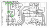
on board (X00-1770-10). I got the signal and now it turns on the relay.
After measuring the pins on both power boards I noticed that:
- pin 12 shows 23.4 VDC, instead of 13 VDC ''A'' (X00-1770-10)
- pin 13 shows -1.6 VDC instead of -7 VDC ''C'' (X00-1790-10)
I would like to ask you for help on how to bring the voltages to the prescribed levels ?
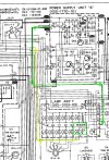
In attachment is Schematic diagram of units ''A'' and ''C''.
Thanky you,
I bought my first vintage receiver, a Kenwood KR-6600 model. I took the cover off and there was a lot of dust in it. I cleaned it all up.
I noticed that the relay does not open when I turn on the device, so after 10-15 minutes it opens by itself.
I replaced with the appropriate components:
- electrolytes (Ck1, Ck2, Ck4-7)..........................Panasonik with low ESR
- metal film resistors Rk1, Rk3 and Rk18
- transistors Qk1 - Qk4
- Diodes Dk1 - Dk4
on board (X00-1770-10). I got the signal and now it turns on the relay.
After measuring the pins on both power boards I noticed that:
- pin 12 shows 23.4 VDC, instead of 13 VDC ''A'' (X00-1770-10)
- pin 13 shows -1.6 VDC instead of -7 VDC ''C'' (X00-1790-10)
I would like to ask you for help on how to bring the voltages to the prescribed levels ?
In attachment is Schematic diagram of units ''A'' and ''C''.
Thanky you,