You are using an out of date browser. It may not display this or other websites correctly.
You should upgrade or use an alternative browser.
You should upgrade or use an alternative browser.
Kenwood KR-6600 power supply board
- Thread starter dimitrije.tu
- Start date

dimitrije.tu
New Member
Hello, after a couple of weeks of using the receiver and successfully repairing the power supply board, I noticed on board "A" (X00-1770-10) resistors Rk1 and Rk3 have changed color.
You will notice in the attached picture the dark color on both blue resistors.
Are any of the components due to failure or wear the cause of the color change on these resistors ?
Is this normal or not ?
Can I use the receiver without fear of something happening ?
You will notice in the attached picture the dark color on both blue resistors.
Are any of the components due to failure or wear the cause of the color change on these resistors ?
Is this normal or not ?
Can I use the receiver without fear of something happening ?
Attachments


The one nearest the regulator is showing signs of being too hot. Measure the voltage across the resistor and using Ohms law figure out how much power it is dissipating.Hello, after a couple of weeks of using the receiver and successfully repairing the power supply board, I noticed on board "A" (X00-1770-10) resistors Rk1 and Rk3 have changed color.
You will notice in the attached picture the dark color on both blue resistors.
Are any of the components due to failure or wear the cause of the color change on these resistors ?
Is this normal or not ?
Can I use the receiver without fear of something happening ?
dimitrije.tu
New Member
Rk1 (metal-film resistor 56 ohms, 2W, +/- 1%)
input voltage 47.8 VDC
output voltage 38.5 VDC
Consumes power ..............1.55 W
Rk3 (metal-film resistor 330 ohms, 1 W, +/- 1%)
input voltage 23.9 VDC
output voltage 5.46 VDC
Consumes power ......... 1,031 W
input voltage 47.8 VDC
output voltage 38.5 VDC
Consumes power ..............1.55 W
Rk3 (metal-film resistor 330 ohms, 1 W, +/- 1%)
input voltage 23.9 VDC
output voltage 5.46 VDC
Consumes power ......... 1,031 W
I think you measured each end of the resistor to ground. Measure across the resistor leads, quicker to figure out. You probably figured it out from your other measurements?Rk1 (metal-film resistor 56 ohms, 2W, +/- 1%)
input voltage 47.8 VDC
output voltage 38.5 VDC
Consumes power ..............1.55 W
Rk3 (metal-film resistor 330 ohms, 1 W, +/- 1%)
input voltage 23.9 VDC
output voltage 5.46 VDC
Consumes power ......... 1,031 W
Rk1 47.9-38.5 9.3 volts across the resistor 1.55 W
Rk3 23.9-5.46 18.44 volts across the resistor 1.03 W Decimal point not a comma , (1,031 watts

 .
.dimitrije.tu
New Member
Hi, after checking and measuring across the resistor leads, I got the following results:
Rk1:
measured value 9.45 VDC
Power consumption 1.60 W
Rk3:
measured value 18.66 VDC
Power consumption 1.06 W
I can see the Rk3 jumping out of the frame a bit.
What is your suggestion for more checks on certain components ?
Rk1:
measured value 9.45 VDC
Power consumption 1.60 W
Rk3:
measured value 18.66 VDC
Power consumption 1.06 W
I can see the Rk3 jumping out of the frame a bit.
What is your suggestion for more checks on certain components ?

FRANKPIETTE
Member
Hello All, i recently partially recap a KR-6600. PSU A & C, Preamp (3 repairs) and both amps. I noticed the 47uF B.P. cap also.
everything went well, i plugged it to the DBT, it turned on, the light lit. Relay won't engage.
1 i unplugged both amps under, still it won't click. I started making measurements
board 1770
1 44.2 VDC
2 23 VDC
3 13.8 VDC
4 Ground
5 -23VDC
6 -44.2 VDC
everything went well, i plugged it to the DBT, it turned on, the light lit. Relay won't engage.
1 i unplugged both amps under, still it won't click. I started making measurements
board 1770
1 44.2 VDC
2 23 VDC
3 13.8 VDC
4 Ground
5 -23VDC
6 -44.2 VDC
Hi, i'm woking on a KR-6600 and my voltages diagram don't match match your. Have you used the KR-7600 as for orange voltages? Or is there two versions? Thanks.i've only worked on one so i'm not an expert and it was returned to it's owner.
I'd focus on "C". Verify bridge is working. measure pins 1, 2. Don't forget a DBT (60-75w bulb).
BTW, pins 11, 12 on "C" are Vac.
View attachment 3465108
Attachments


FRANKPIETTE
Member
Hello all, my turn to work on a Kenwood KR-6600. I recapped PSU A, C, preamp, both amps. The old relay was clicking before, now it won't click on the DBT.
I didn't miss the Bipolar cap, everything went fine as for the job. I check all caps for polarity, checked solders.
1-I unplugged both amps from the bottom connectors. Then I turned the unit on again; still not clicking in.
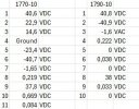
I took voltages at 1770-10 and 1790-10
I didn't miss the Bipolar cap, everything went fine as for the job. I check all caps for polarity, checked solders.
1-I unplugged both amps from the bottom connectors. Then I turned the unit on again; still not clicking in.
I took voltages at 1770-10 and 1790-10