• The move to the new server is done. There are some software and database maintenance updates in process. This has us passing the hat around to help out. We appreciate any donations. Seriously, even a dollar helps. The payment page may be found here - https://www.audiokarma.org/support.html

Kenwood KR-790 issue

Anonky

Kenwood KR-9600 / Pioneer SX-950 / Sony STR-GX10ES
Hi all,

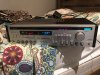
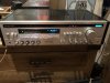
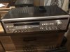
Picked up a seemingly rare bird yesterday. Kenwood KR-790. 130wpc. Crazy cool 80s front display, dark wood case. Looks like it belongs in a space shuttle. Condition is almost perfect albeit missing one of its four feet which I’m rigging up a makeshift replacement for.. At first it appeared to function fine, but after running for a little while I noticed it was running quite hot. This is likely a combination of my poor placement of the unit on the bed (see photo.. I had no other space to set it). Once I noticed how hot it was running, I powered it down then unplugged it. Feel really stupid about putting it on the bed because it obviously impaired ventilation, and I’m afraid I may have damaged something. It is only turning on maybe 1/4 of the times I’m attempting to turn it on for some reason. I just got this last night and wasn’t able to have it demo’d prior to purchase so I’m not sure if this was its baseline function prior to purchase or if I possibly damaged something.

To clarify, it HAS turned on and functioned since this occurred, just maybe a quarter of the times I’ve attempted to power it on. The insides are incredibly dirty so I’m first going to open it up and give it a good “blow job” then go from there.

Considering all this, I have a few questions. There are a few lamps that I can tell are out. Where can replacement LEDs be obtained? I’ve got an o-scope and have gotten handy with soldering so if there is an issue I’m sure I can fix it. Have a play date with an electrical engineer bud of mine to go through a few of my pioneers and I might need to add this to our to do list. Where might you direct your attention considering the intermittent nature of this problem? A loose/cold joint perhaps in the power supply? If it was a blown fuse I imagine it wouldn’t have powered back on at all.

I’m still new at this. Any advice is greatly appreciated as I would love to get this back to its former glory!
 

Attachments
  • 097EDBBD-4C49-49FC-B451-D023569EE14B.jpeg
    097EDBBD-4C49-49FC-B451-D023569EE14B.jpeg
    82.4 KB · Views: 31
  • ED60F6FD-4420-4F16-9725-4CA282C6CDA8.jpeg
    ED60F6FD-4420-4F16-9725-4CA282C6CDA8.jpeg
    136.5 KB · Views: 29
Last edited:
Register to hide this ad
If you can get it to turn on, check DC offset and check bias of the outputs.

High bias current could explain running hot.
 
Last edited:
Picked up a seemingly rare bird yesterday

There are a few lamps that I can tell are out. Where can replacement LEDs be obtained?

You probably have read the many KR-790 threads on AK. Here is one about bulbs, links to schematic, ...

https://audiokarma.org/forums/index...tempt-at-resurecting-a-kenwood-kr-790.836724/

I'd blow out the dust (outside) and like @spark1 suggests, check DC offset and bias levels. post results. if these are good, we will need more investigation.

Feel free to post a pic or two of the inside.
 
You probably have read the many KR-790 threads on AK. Here is one about bulbs, links to schematic, ...

https://audiokarma.org/forums/index...tempt-at-resurecting-a-kenwood-kr-790.836724/

I'd blow out the dust (outside) and like @spark1 suggests, check DC offset and bias levels. post results. if these are good, we will need more investigation.

Feel free to post a pic or two of the inside.
Thanks for the info! Will try to do this later tonight. I’ll take a nice before and after blowjob pic.
 
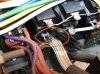
I’ve opened it up. I’ve yet to check the dc offset or blow out the inside, but this wet look area caught my eye. Looks fresh too. Would this mean I likely have a blown cap?

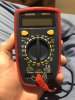
To check dc offset which setting on my multimeter do I need to set to check the dc offset? See photo. Thanks for entertaining rudimentary questions. I’m learning. Thanks again.
 

Attachments

  • E309CD43-C6F6-4773-B54D-C87CCC702D8E.jpeg
    E309CD43-C6F6-4773-B54D-C87CCC702D8E.jpeg
    138.6 KB · Views: 18
  • 5195C35C-1566-4AFA-A79A-F419246202B1.jpeg
    5195C35C-1566-4AFA-A79A-F419246202B1.jpeg
    212.2 KB · Views: 19
  • 3BF40408-4980-46B6-80AD-F04E68452D6E.jpeg
    3BF40408-4980-46B6-80AD-F04E68452D6E.jpeg
    98.2 KB · Views: 18
If those caps were leaking, it would be centered under them...unless it vented out at high pressure, in which case there would be evidence of that. Do those caps show any splitting or other damage?

Is this under the vented top of the case?

DC, mV. No input, selector on AUX, volume at zero, no speakers connected. Speakers off. Power on, connect probes to right speaker terminals. Activate speaker switch. Read meter.

Speakers off. Move probes to left speaker terminals. Activate speaker switch. Read meter.

Ideal is zero mV. Under 50mV is ok. Don't confuse volts and millivolts.

Unit looks like it was stored in a barn.
 
If those caps were leaking, it would be centered under them...unless it vented out at high pressure, in which case there would be evidence of that. Do those caps show any splitting or other damage?

Is this under the vented top of the case?

DC, mV. No input, selector on AUX, volume at zero, no speakers connected. Speakers off. Power on, connect probes to right speaker terminals. Activate speaker switch. Read meter.

Speakers off. Move probes to left speaker terminals. Activate speaker switch. Read meter.

Ideal is zero mV. Under 50mV is ok. Don't confuse volts and millivolts.

Unit looks like it was stored in a barn.
I’ll inspect more closely but they didn’t obviously appear to be bulging or cracked as far as I could see. They are on the edge of the vented area directly below, so I suppose it could’ve been liquid from outside that came in from the top. Will investigate more
 
Problem I’m having now is it seems that getting it to turn on is more and more scarce and I can’t figure out why it turns on sometimes but not others? I’m going to clean it out once this compressed air comes in the mail then update probably Thursday night.
 
Once or twice the IF band light came on last night but nothing else then it goes out. Other times it seems total failure to power up. I’m not going to fool with it anymore til I’m able to clean it out then I’m going to try to power it on again. Again, this will probably be Thursday night as I’m waiting for compressed air. I’m just afraid I’m exacerbating the problem repeatedly powering it on and off with no results.
 
I should also clarify that the power light is one of the lamps I need to replace so the light doesn’t come on when it’s powered up. Other than seeing other lights on the unit turn on is how can I tell if it’s in protection mode etc?
 
Search for "dim bulb tester". You can limit current with it, reducing chances of chain reaction failures due to short circuits.
 
build a DBT and start using it. No need to break more parts.

oops. Looks like sparks beat me to it.

once you get it built, check the PS voltages to see if the voltage rails are correct. it will be lower than the schematic so post your measurements.
 
Update: picked up some compressed air and blew out all the dust and hair. After this I did some closer inspection probing joints etc with the eraser end of a pencil (safety first!) and noticed a poor connection where the power cord comes in and binds to a post. There is also a power outlet on the back of the receiver that also binds to this common post but it wasn’t soldered on? It is simply wrapped but doesn’t have great contact. I probed a bit with the unit plugged in but off and got a tiny spark. Interesting. Figured why not and powered it up. Bingo. It turned on. It must’ve been in just the right position making good contact. Assuming this is the only issue, I should be able to just solder this poorly wrapped wire into place and be back in business yeah?
 

Attachments

  • BB219B75-3864-4019-BBA3-71DDE3AB9F2B.jpeg
    BB219B75-3864-4019-BBA3-71DDE3AB9F2B.jpeg
    117.1 KB · Views: 12
Reflowed some solder on this post and… IT’s ALIVE! Powered off and on several times now without failure so we are good! I’m still going to do to check dc offset and perhaps adjust bias to optimize its function. Also going to reach out to that guy from the post in @rickl ’s response. Looking for 4 bulbs to replace dead ones. If anyone has some I’m happy to pay a reasonable price for them. WOOO!
 

Attachments

  • 16E8F641-4A46-41AF-AB15-54ECDEC40B1E.jpeg
    16E8F641-4A46-41AF-AB15-54ECDEC40B1E.jpeg
    120.3 KB · Views: 9
  • 4283E6D8-AEDA-4961-BEF6-04C0BA8C1831.jpeg
    4283E6D8-AEDA-4961-BEF6-04C0BA8C1831.jpeg
    100 KB · Views: 7
Re protection relay. You should be able to hear it clicking when (if) it closes, shortly after powering it up.

Re bias; this is something that must be done with great care as it easy to short across something when working in tight quarters. Using mini-grabbers instead of probes is highly recommended, as is making/breaking connections with power off. Without a manual to specify correct bias, you will basically be comparing one channel to the other to get an idea if one is out of whack. In the absence of a spec, I would say that anything above 40mA or so might be cause for concern. Some amps are biased higher, but this is not common...and correct bias for many amps is quite a bit lower than that. Bias measurement and adjustment is normally done after warming up the amp for ten minutes or more.
 
Re protection relay. You should be able to hear it clicking when (if) it closes, shortly after powering it up.

Re bias; this is something that must be done with great care as it easy to short across something when working in tight quarters. Using mini-grabbers instead of probes is highly recommended, as is making/breaking connections with power off. Without a manual to specify correct bias, you will basically be comparing one channel to the other to get an idea if one is out of whack. In the absence of a spec, I would say that anything above 40mA or so might be cause for concern. Some amps are biased higher, but this is not common...and correct bias for many amps is quite a bit lower than that. Bias measurement and adjustment is normally done after warming up the amp for ten minutes or more.
I can definitely tell the left channel is more powerful just listening. Ok so to be clear I do measure dc offset and adjust the bias with the unit powered on after 10 mins of warmup, yes?
 
Do you know how to measure the bias? And how the adjustment is made? Or even if it can be adjusted on this unit?

In any case, just measure both offset and bias, then post results before messing with adjustments.

An output difference is unlikely to be related to issues with bias or offset.
 
Do you know how to measure the bias? And how the adjustment is made? Or even if it can be adjusted on this unit?

In any case, just measure both offset and bias, then post results before messing with adjustments.

An output difference is unlikely to be related to issues with bias or offset.
Someone else posted instructions that are straight forward enough further up in the thread. I watched a YouTube video of a guy adjusting bias in one of the lower models from this line and it appears there were two potentiometer looking things to on a board that you rotate. When I opened it up I saw one identical to what was seen in this video but I’ve yet to locate a second one. There may not be a second one?
 
I don't see those instructions, but if you have them, and they are pertinent to this unit, follow them instead of listening to me.

Bias and DC offset adjustments, if available, are per channel...one for right, one for left. I suggested just measuring and posting, but it looks like you plan to move forward. Good luck with it.
 
Back
Top Bottom