• The move to the new server is done. There are some software and database maintenance updates in process. This has us passing the hat around to help out. We appreciate any donations. Seriously, even a dollar helps. The payment page may be found here - https://www.audiokarma.org/support.html

Kenwood KR-9400 surprise: op-amps

repo_code

somewhere in the 20th c.
Were op-amps common on vintage TOTL receivers?

The "TONE AMP" PCB on the -9400 has three op-amps per channel; Tone Defeat bypasses two. The phono, AM/FM, and MIC inputs go through another one at the input selector.

There are also op-amps outside the signal path, in the IF section, driving the meters, etc.

Do op-amps in the signal path deserve their reputation for meh sound quality or can a good IC implementation keep up with discrete? Can you upgrade vintage op-amps with modern equivalents for better sound?

My other vintage reciever is a Sanyo 2600K that's fully discrete except for one op-amp, in the phono stage. Everything else including the tuner is fully discrete. I was surprised to see so many ICs on the Kenny, being 5 years older and TOTL.
 
Register to hide this ad
Personally, I think they can more than keep up. IC designers have really tight control over the parameters of their circuit, much more so than someone designing a circuit on a PCB with discretes. I think the reputation came from some early implementations which were maybe not that great. But companies such as Analog Devices really knew what they were doing when it comes to audio. Well, electronics in general.

Some very sought after and respected analogue mixers, such as Neves, Calrecs ... use opamps. As do many other pro-audio products.

Do a google on the "5$ preamp" ...
 
Here we go. One of the channels' bias was set real low, only 10mV.

So I was probably hearing some crossover distortion and looking for an explanation of why it sounded garbagey. This machine cost $750 when a typical car cost $4000. Opamps and all, it should sound OK.
 
Update: the sound on this unit is better but still just OK, and I'd like to fix that. TOTL should sound better than this.

I replaced the differential pairs on the power amps, bringing DC offset down to ~5mV on each channel, and recapped the power amps.

The sound is good but not great. Lows and mids can be impressive. The highs are off, they sound dim and mushy. Detail is distorted.

When using the AUX input with tone defeat, there are only two gain stages between that input and the speakers: the power amp, and one TA7136 op-amp per channel on the tone amp.

I may replace those op-amps on the tone amp with something modern. This looks doable. For example, you can get a 7136 adapter from a site called BrownDog for a modern 8-pin DIP package single op-amp and plug in an OPA627. Someone else sells a 7136 adapter that fits a dual op-amp so you could use for example an AD823. Both have specs that smoke the TA7136 (1% THD vs 0.1% THD and so on.)

It's just a guess that the TA7136 is at issue, an o-scope would say for sure.
 
Other factors can affect the amps in the ways you describe. Upgrading to newer low noise Op Amps can help, but only if the original design were well thought out and used top grade components.

It is questions like this that bring to mind my Brother's old Rotel SS amp. It sounded "okay", but there was nothing to really compare it to, and when one channel died, I located and replaced the transistors in that stage only (initially), and when I fired it up, the repaired channel was very quiet and had clean sound reproduction. The difference was in the fact the replacements I used were Military Spec'd transistors that had been surplus. This was also one of the first SS amps i had worked on to that extent, so I was surprised that there was that much difference in sound from just upgrading 2 transistors. The other channel was upgraded with the same replacements as soon as I was able to secure some additional stock. So if you are going to try an upgrade, do one channel at a time so you can compare.

AD and MicroChip have some real good prospects for upgrading. But if your results are less than stellar, the issue may be elsewhere. Leaky filter caps, or other components that are out of spec and pull the supply rails down in voltage or in other ways limit current should be evaluated first. Filter caps, the power rectifiers, carbon composition resistors, etc, even leaky transistors int he regulator circuit can do this if the audio stages are common at power supply.
 
This is interesting, op-amps are class A/B push-pull devices and you can bias them into class A

The theory is that in class A you would see no crossover distortion and you can force the op-amp to only use its NPN output drivers which are likely faster than the PNP drivers. It might sound better.

There's a Brown Dog adapter and a pair of OPA627's heading my way. I'm planning to add a 22K resistor from the op-amp outputs to the B- rail (-14V) to bias it into class A by drawing a more or less constant .6mA from the op-amp output.

Kenwood did not bias the original TA7136 into class A for some reason...
 
Mod is done! CAUTION if you attempt...

A warning for anyone doing this mod: on one of the BrownDog adapters (and not the other) some of the pins weren't actually connected to the traces on the circuit board. This took a few seconds to fix with the soldering iron, after an hour finding the problem. :no:

So, check connectivity from the pins on the adapter to the pins on the IC before soldering the adapter deep down into the bowels of your vintage gizmotron.

After the mod, some of the treble that was dim before is more pronounced. Overall tonal balance is more neutral. I can't say more about the sound until my sinus infection clears and my ears drain out.
 
A warning for anyone doing this mod: on one of the BrownDog adapters (and not the other) some of the pins weren't actually connected to the traces on the circuit board. This took a few seconds to fix with the soldering iron, after an hour finding the problem. :no:

So, check connectivity from the pins on the adapter to the pins on the IC before soldering the adapter deep down into the bowels of your vintage gizmotron.

After the mod, some of the treble that was dim before is more pronounced. Overall tonal balance is more neutral.
I can't say more about the sound until my sinus infection clears and my ears drain out.
Interesting...

Do you have a picture of it?
 
Some units did use the STK blocks, your Kenwood and it's upper end sibling, the KR 9600 major offenders. I prefer discrete transistors.
 
Do you have a picture of it?

No, I'm a bad internet citizen and didn't get a pic before installing the thing.

Each pin on the adapter is shaped like a little C-clamp, each end of the 'C' contacts a pad on one side of the board. You can sort of see that here, this is a pic of a different adapter that uses similar construction:

bd040701.jpg


The factory only bothered to solder one end of the 'C' to one side of the board. But only for some pins; other pins were soldered on both sides, seemingly at random.

The two sides aren't interchangeable. The pads on the front of the board are connected to the contacts for an SMD, the pads on the rear of the board are connected to the contacts for a DIP. So the factory should have soldered up all of them.
 
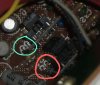
Here's a pic.

Circled in blue: the C-clamp-shaped pins are joined to the pads with solder. The pads are gold, and you can't see any gold here, as it's all covered by solder joints like it should be.

Circled in pink: the C-clamps are not joined to the pads. The pads (gold) are entirely visible and there's a tiny air gap between each pad and pin. If you were trying to use an SMD op-amp with this adapter you'd have open connections.
 

Attachments

  • bug.jpg
    bug.jpg
    104.3 KB · Views: 130
Last edited:
Looks very well done! Nice!

I replaced all the 5532 I had for the OP2604. I think the soundstage is wider, sound is overall warmer. Channel separation is better to my ears.

Two OPA627s must be very good, being these single op-amps.
 
Update. I removed the 3pF capacitors (Ci29, Ci31) from the output of the OPA627.

These were external compensation caps for the TA7136. They serve no purpose for a modern opamp with internal compensation. Worse, they will look like a parasitic load, so they're gone.

I also removed coupling caps Ci27, Ci28 and resistors Ri39, Ri40. The opamp output is now direct-coupled to the output of the TONE PCB.
 
To bias the op-amps into class A, I used method 2 on Warren Young's page.

The bias network runs from opamp output, to a 300 ohm resistor, to a .91mA current regulating diode (CRD), to the -14V rail.

This is theoretically better than using eg. a 22K resistor. It gives constant bias current regardless of supply voltage ripple. It also presents a higher impedance to the opamp. The 300 ohm resistor is there to prevent the opamp from seeing directly into the picofarad-range input capacitance of the CRD.

It's theoretically worse than what Young calls method 3...
 
This KR-9400 is the gift that keeps on giving. I found a new design bug today on the TONE AMP PCB.

There's a coupling cap at the inputs to this PCB, in front of the opamp. It's a polarized tantalum cap rated 0.47uF and 35V. And, the cap is backwards! It will be reverse polarized (albeit by much less than a volt) all the time. If the opamp uses NPN transistors at its inputs, it will draw current away from the + side of this cap and slightly reverse bias it. (Both the original TA7136 and the replacement OPA1611 opamp have NPN inputs.)

What happens when you reverse-bias a polar cap? Does it behave nonlinearly? Does it fail early? This is EE 101 stuff, you aren't supposed to reverse bias a polar cap, the results are never guaranteed -- I think that's the rule of thumb.

I replaced these caps with jumpers tonight and the sound was immediately less veiled. I did them one at a time, so had the chance to do a side-by-side left channel vs. right channel comparison and the improvement was clear. So that's nice.

Merry Christmas :D
 
Here's a bonus bug, also on the TONE AMP PCB.

Filter caps Ci23 and Ci24 are rated for 10V max, which is exceeded in this design, the rails are +14V and -14V. So there's that. Not sure if I've mentioned that before.

My girlfriend replaced these with 25V caps. She did a lot of the soldering on this Kenwood. Thanks hon! She listens for differences in SQ too.

The new filter caps didn't change the sound, but I feel better with everything running within spec.

Who designed this Kenwood? It had so many design bugs.
 
Tone amp 7136 replacement

Having read the various posts on the 7136 replacement, including:

http://www.audiokarma.org/forums/showthread.php?t=540756

http://www.diyaudio.com/forums/parts/46179-replacement-ta7136p.html

the following is what i have undertaken for those that may have the same issues.

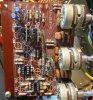
I purchased the Browndog PCB's and mounted OPA604 IC's on them (see attached pictures). I have also added sockets for the 4558 IC's, and will install new 4558P IC's in place of the original JRC metal can types.

as per the various posts the following mods have been undertaken"

remove C1 and C2 (0.47uf tantalum) and replace with links
remove Ci29 and Ci31 3p ceramics (which are freq compensation for the original 7136)
Replace Ci23 and Ci24 with 47uf 25 volt electros (I use Nichicon KA, but PW are also favored)-the ones pulled out measured about 30uf each
replaced Ri1 and Ri2 (2.2k) with metal film 1% resistors as they are directly in the signal path
Replaced the high value (2.2M) carbon resistors with metal film 1%

and then there are 10 6.8uf 10v Non Polar electro caps, which I will replace as well.

all of this in search for a discrepancy in volume between the two channels, which is in the pre amp part of the amp.

pictures of partially completed board attached (ignore the screw it is just there to get the photo)
 

Attachments

  • IMG_0225.jpg
    IMG_0225.jpg
    91.7 KB · Views: 58
  • IMG_0226.jpg
    IMG_0226.jpg
    57 KB · Views: 51
  • IMG_0227.jpg
    IMG_0227.jpg
    67 KB · Views: 48
Last edited:
pwauk12...

I just finished re-capping the amp boards and performing the service bulletin on my KR 9400.

I intend to change out the previously mentioned resistors and caps on the tone board also.

I'll probably wait to change the op-amps until I have a chance to evaluate the effect of the work done to this point.

My question is what replacement capacitor looks good for the (10) - 6.8uf 10volt electrolytic caps??? A worthwhile application for a film caps here?

Just curious for opinions.
 
Back
Top Bottom