• The move to the new server is done. There are some software and database maintenance updates in process. This has us passing the hat around to help out. We appreciate any donations. Seriously, even a dollar helps. The payment page may be found here - https://www.audiokarma.org/support.html

Kenwood KR-9940 DC offset & basic tuneup Qs

Puddintane

Super Member
I’m trying to do a basic cleanup and check up on a Kenwood KR-9940 beast owned by a family member. My first question is, does this thing have adjustable DC offset? Or is it cap coupled? I’ve gone through a couple lengthy threads here on rebuilds for this unit, and that kind of in-depth restoration is not on the table here. I’m just trying to think of basic tuneup things that can be done, hopefully, without replacing components. Its owner will use it as a two-channel stereo, so quad functionality isn’t really a concern. Although it might also be used as an A+B setup to power speakers in a couple separate rooms. But that’s about it. Thanks in advance for your input.
 
Register to hide this ad
I’m trying to do a basic cleanup and check up on a Kenwood KR-9940 beast owned by a family member. My first question is, does this thing have adjustable DC offset? Or is it cap coupled? I’ve gone through a couple lengthy threads here on rebuilds for this unit, and that kind of in-depth restoration is not on the table here. I’m just trying to think of basic tuneup things that can be done, hopefully, without replacing components. Its owner will use it as a two-channel stereo, so quad functionality isn’t really a concern. Although it might also be used as an A+B setup to power speakers in a couple separate rooms. But that’s about it. Thanks in advance for your input.
Not cap coupled. Nice and attractive set but should be, needs to be thoroughly cleaned, switches and controls and known for certain issues, differential input transistors on main amp board should be replaced but if working properly might leave it alone. Not looking at schematic but quite certain amp has offset as well as bias adjustment. Those are not easy to work on but can be made quite reliable. They are very attractive, my opinion.
 
Not cap coupled. Nice and attractive set but should be, needs to be thoroughly cleaned, switches and controls and known for certain issues, differential input transistors on main amp board should be replaced but if working properly might leave it alone. Not looking at schematic but quite certain amp has offset as well as bias adjustment. Those are not easy to work on but can be made quite reliable. They are very attractive, my opinion.
Thanks for your input. Please pardon my ignorance, but if it is not cap coupled, then shouldn’t it have an adjustment for DC offset? How does one measure this for DC offset? Set to 2-channel, dummy load to A, measure at B?

Also, I read this thread and I’m confused about where he’s connecting emitter resistors for setting the bias. Is it just across each leg of the resistor? This thread (not sure why, but all the editing buttons are grayed out in this reply box so that I can’t insert a hyperlink other than pasting the full URL):
 
Thanks for your input. Please pardon my ignorance, but if it is not cap coupled, then shouldn’t it have an adjustment for DC offset? How does one measure this for DC offset? Set to 2-channel, dummy load to A, measure at B?

Also, I read this thread and I’m confused about where he’s connecting emitter resistors for setting the bias. Is it just across each leg of the resistor? This thread (not sure why, but all the editing buttons are grayed out in this reply box so that I can’t insert a hyperlink other than pasting the full URL):
Busy day here. I am quite sure it has offset for each of the four channels as well as bias adjustment. I would have to look at the schematic/manual to further comment, you should acquire, in some ways it is very straightforward but made more complex and a bit difficult by virtue of having four discreet amplifiers in one package. I would need to read the manual, see the schematic but quite sure all adjustments to amplifiers are made in four channel mode. Offset, if relay clicks, is measured at speaker outputs with load connected. If relay does not click, protection, then that issue must be fixed first. If relay clicks then one can proceed to other things, if desired. If not familiar with repair that is quite a unit to start out with... not to deter, just saying it is kind of a beast. At any rate, hopefully others will chime in and offer benefit from their experience.
 
Busy day here. I am quite sure it has offset for each of the four channels as well as bias adjustment. I would have to look at the schematic/manual to further comment, you should acquire, in some ways it is very straightforward but made more complex and a bit difficult by virtue of having four discreet amplifiers in one package. I would need to read the manual, see the schematic but quite sure all adjustments to amplifiers are made in four channel mode. Offset, if relay clicks, is measured at speaker outputs with load connected. If relay does not click, protection, then that issue must be fixed first. If relay clicks then one can proceed to other things, if desired. If not familiar with repair that is quite a unit to start out with... not to deter, just saying it is kind of a beast. At any rate, hopefully others will chime in and offer benefit from their experience.
Yeah, I fired it up with the DBT last night with no load or source and let it idle for about a half an hour. Relay clicked and seemed to pass the basic power up test anyway. But didn’t do anything more at that time.
 
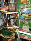
Couple other questions/issues. While doing a little visual inspection I came across these three capacitors on the power supply board. Is that glue overrun or something else? The way it strings up from the bottom on a couple of them, and also as it’s found at the base of one of the big caps on the main amp board, makes me wonder. Although the middle one of the three circled caps looks a little suspicious. Also, the big cap on the main board is supposed to be a 220mf/35V and it looks like it’s a 220/50V. Don’t know if that would’ve been done in the factory or what. As far as I know, this thing has never been tinkered with. I don’t know if this matters or not, but the label number on the main board varies from the diagram in the service manual a bit, as far as the suffix at the end. This one’s got -10 printed on it, but that’s not shown as an option in the manual.

IMG_5265.jpegIMG_5282.jpegIMG_0074.jpegIMG_0075.jpeg
 
The caps, I'd say it is factory glue from assembly. The higher voltage cap, not a problem, easily be factory for a variety of reasons, parts on hand or an upgrade deemed advisable that didn't make it to the schematic. Don't know about the board numbers. I see two relays, one for each pair of amplifiers, twin contacts. It sounds/looks like you have a working cherry to proceed with. You mentioned the service manual, good you have one, it might explain much about the design and circuit operation, back then many did.
 
Well, unfortunately my ability to use a schematic extends only to getting lucky enough once in a while to matching up a component on a circuit board to it’s ID on the diagram. Can’t really trace or analyze a circuit or figure out much else anything about it.
 
I understand that you are not seeking a full restoration and a simple clean-up, but consider that this receiver was manufactured from 1972 to 1974 and is more than 50 years old. If you do not replace the caps, you will not be able to set the DC offset and Bias.
And if I were you, I would test with a dummy load, instead of using the speaker, a higher DC offset (more than 100mV) can damage your speakers, and also for safety, you should use a DBT before powering it.
 
Well, unfortunately my ability to use a schematic extends only to getting lucky enough once in a while to matching up a component on a circuit board to it’s ID on the diagram. Can’t really trace or analyze a circuit or figure out much else anything about it.
It is working and apparently working correctly. Play some music through it. Only change the 2ch/4ch switch on the back when the unit is off, this is important. If at idle all the heat sinks are the same temperature it might be good to assume the bias is okay. If the offset was far enough off to be a real concern the protection relay would not click. The reason I am saying this is because it's very easy to short something with a probe setting bias, or something, and have a spark followed by the power fuse blowing. It is the adage of looking for trouble and you'll find it. On the other hand that set is quite old and bound to have issues in the not so distant future and, it would probably sound better if serviced, coupling caps throughout replaced, etc. If it was your own and you planned to keep it I'd say tear into, cautiously as you read up on it from different sources, electronic repair in general. I thought those were one of the most elegant looking quad receivers yet they do have pattern failures that if addressed are quite reliable. Love the lighting and the meters.
 
I understand that you are not seeking a full restoration and a simple clean-up, but consider that this receiver was manufactured from 1972 to 1974 and is more than 50 years old. If you do not replace the caps, you will not be able to set the DC offset and Bias.
And if I were you, I would test with a dummy load, instead of using the speaker, a higher DC offset (more than 100mV) can damage your speakers, and also for safety, you should use a DBT before powering it.
I get all that, and if it were my personal gear, I might consider it. Although this probably wouldn’t be my first choice for my first foray into recapping! I also have a soon-coming commitment to return it when the owners come for a visit. And it’s going back home with them halfway across the country now, or else there won’t be another opportunity for quite a long time. What I’d like to do is at least measure the offset and the bias to see if it’s close enough, or can be set for now. If it’s got any serious issues, I’ll probably just return it to them and let them decide if they want to leave it with me for now, or pay someone in their home area to deal with it.
 
I’ve read these two threads (here and here) and am still unsure about how to (a) adjust the offset (if it’s possible), and (b) how to connect to measure the bias. As to (a), where are the varistors (or maybe better, are there any?)? As to (b), in the first thread the OP Talks about his Connecting to the leads because of the placement of the resistors in from the looks of it the wiring in that area. The unit I have it’s very different looks much neater and easily accessible. I guess my question is this: is he just connecting across each leg of the big resistor in there for each channel? The SM is a little vague (or perhaps too general for my level of understanding). A specific explanation would be greatly appreciated.

IMG_0077.png
 
I’ve read these two threads (here and here) and am still unsure about how to (a) adjust the offset (if it’s possible), and (b) how to connect to measure the bias. As to (a), where are the varistors (or maybe better, are there any?)? As to (b), in the first thread the OP Talks about his Connecting to the leads because of the placement of the resistors in from the looks of it the wiring in that area. The unit I have it’s very different looks much neater and easily accessible. I guess my question is this: is he just connecting across each leg of the big resistor in there for each channel? The SM is a little vague (or perhaps too general for my level of understanding). A specific explanation would be greatly appreciated.

View attachment 3544072
Looking at the amp schematic from the link I don't see an offset adjustment, would have expected it. Offset would be determined by how well the differential transistors of the input track each other, supposed to be matched. The varistors are the series shown diodes labeled as STV-3H, mounted to the heat sink.

For idle, yes, at idle, heat sink cool, not warm, measure voltage across the big .47 ohm resister, emitter resistor of output transistor as shown. Unit must be powered on to do this so be careful, so easy to bridge something and ruin the day. Sometimes those trim resistors become intermittent when disturbed, very bad, ruins an otherwise good day. I've never had one fail but it happens, always on my mind when adjusting bias. Idling, if heat sinks all feel the same the bias is most likely okay and don't require attention though am sure it could be tuned up, not something you would hear, or, if you could would be at very low volume. I'd leave it alone.
 
Last edited:
Looking at the amp schematic from the link I don't see an offset adjustment, would have expected it. Offset would be determined by how well the differential transistors of the input track each other, supposed to be matched. The varistors are the series shown diodes labeled as STV-3H, mounted to the heat sink.

For idle, yes, at idle, heat sink cool, not warm, measure voltage across the big .47 ohm resister, emitter resistor of output transistor as shown. Unit must be powered on to do this so be careful, so easy to bridge something and ruin the day. Sometimes those trim resistors become intermittent when disturbed, very bad, ruins an otherwise good day. I've never had one fail but it happens, always on my mind when adjusting bias. Idling, if heat sinks all feel the same the bias is most likely okay and don't require attention though am sure it could be tuned up, not something you would hear, or, if you could would be at very low volume. I'd leave it alone.
So one mini grabber on each leg of all eight resistors? Do I measure them all separately, and which pot controls which one? (Appreciate your patience. I’ve done this a few times before, but it’s been a few years ago, and it was an easy procedure with designated measuring pins and a pot for each channel). Like I mentioned before, in one of the posts above the OP was facing some challenges connecting because the wiring was coming up out of the top and over the resistors making access difficult. In the unit I’m dealing with the wiring is all very neatly tucked down inside of the heat sink and the legs of the resistors are easily and safely accessible. Also, I think I may have used the wrong terminology. I said varistor, but what I was referring to was VR1-VR4 (variable potentiometer) on the main board. Those are used to adjust the bias, correct?

IMG_5255.jpegIMG_5259.jpeg
IMG_5260.jpeg
 
Vr1 through 4, yes, bias. They will be in line down the board to the emitter resistors of their channel. Measure MV across one resistor, mini grabber on each leg, for each channel, either one of the two, for a total of four, one for each channel. That is a good example of the 9940, doesn't look like anybody has messed with it. Pulling the driver board and heat sink can get involved, wires and stuff everywhere. If not already, you should take many pictures showing wires and places they go in case one or a few get loose should you take things apart, sometimes they seem to do it just looking at them. This stuff is getting old.
 
Vr1 through 4, yes, bias. They will be in line down the board to the emitter resistors of their channel. Measure MV across one resistor, mini grabber on each leg, for each channel, either one of the two, for a total of four, one for each channel. That is a good example of the 9940, doesn't look like anybody has messed with it. Pulling the driver board and heat sink can get involved, wires and stuff everywhere. If not already, you should take many pictures showing wires and places they go in case one or a few get loose should you take things apart, sometimes they seem to do it just looking at them. This stuff is getting old.
Thanks, exactly what I needed to know. Oh, are dummy loads needed/used for biasing, or just for offset? (I’ve always used crap speakers in the past but finally broke down and bought some proper 8ohm/100w ones from P-Express.)
 
Thanks, exactly what I needed to know. Oh, are dummy loads needed/used for biasing, or just for offset? (I’ve always used crap speakers in the past but finally broke down and bought some proper 8ohm/100w ones from P-Express.)
Loads don't really have to be connected for bias adjustment since it does not flow through the speakers, no signal though in either case. Sometimes it is specified to have a load connected but I wouldn't worry about it, service manual thinking for the unit as a whole. I want to add, giving advice when I'm not there to confirm everything is not something I like to do, can't take responsibility. Double check everything each step along the way.
 
Should the bias reading be somewhat instantaneous or might it creep up? I hooked onto one resistor and powered it on and it started out at 20 mV and over 5-10 minutes slowly crept up to 30. The unit was good and warmed up, since I’ve had it powered on for 45 minutes to an hour at this point tinkering with the DC offset at all the different speaker jacks.
 
Last edited:
Okay, I’m getting some odd readings. As I’m trying to compare your instructions of the resistors that go with each channel, I had in mind the photo from this post where the OP put tape tags for each channel. They run from left to right (immediately behind the main board) Q3, Q4, Q1, Q2 and in the rear (closest to the speaker jacks) it’s Q8, Q7, Q6, Q5. So I am assuming that VR1, which is directly in front of Q3 and Q8 (front to rear) controls that channel, VR2 aligns with Q4 and Q7 and so forth across left to right (i.e., Q1/Q6, Q2/Q5). (Same as the labels in this other post.) So if I’m connected to the resistor on either Q3 or Q8, I adjust VR1. Connected to either Q4 or Q7 I adjust VR2 and so forth from left to right. Am I on the right track?

Edit: I snagged the pic below from the referenced post and corrected my incorrect descriptions of the channel.

IMG_0079.jpeg
 
Last edited:
Back
Top Bottom