• Please note that Audiokarma will be offline briefly for updates early on Monday morning, September 28th.

Kenwood KR-9940 DC offset & basic tuneup Qs

When I did one, I set the bias following EW's post

you must let it warm up for 20-30 minutes and on mains Vac.
 
When I did one, I set the bias following EW's post

you must let it warm up for 20-30 minutes and on mains Vac.
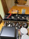
Thanks, I hadn’t seen that thread. Did you happen to see my last post here above (#20) prior to yours with the image of the “Q” labels on the transistors? Can you shed any light on my question about the channels and testing points? I’m not entirely sure where to attach and then which Vr controls which. I’m confused because I had my grabbers connected to each leg of the resistor for Q3 ( correct?), but it gradually rose up to about 30 mV, although VR1 was set fully counterclockwise at its minimum. Appreciate your help. I‘m not confident that I follow EW’s description, and it’s hard to tell from your photos what you’re hooking onto.
 
Loads don't really have to be connected for bias adjustment since it does not flow through the speakers, no signal though in either case. Sometimes it is specified to have a load connected but I wouldn't worry about it, service manual thinking for the unit as a whole. I want to add, giving advice when I'm not there to confirm everything is not something I like to do, can't take responsibility. Double check everything each step along the way.

Precautionary statements appreciated and understood. I’m about to dig into this thing again after being out of town for the last week or so. I’ve been reading echowars’ post (that @rickl said he relied on when he worked on one of these) and looking at the schematic, and I’m hoping you/someone can help me understand this better before I start tinkering again. As I asked in my post above (#20), I’m unsure about (1) which specific pairs of transistors (Q1-Q8) form a matched channel, (2) which one of them I need to be connected to with my mini grabbers when I’m adjusting, and (3) which pot (VR1-VR4) controls which resistor/pair of resistors/channel. Can I connect to just one (of either of them) for any given channel and make the adjustment? Again, your help and patience with my noobness is much appreciated.
 
Last edited:
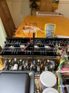
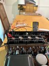
I decided to clean the bias pots with some contact cleaner, as they were very jumpy and sticky. I’ve been able at this point to adjust to normal readings for the Q3, Q4, Q7, and Q8 “channels” (I’m still not sure at this point the that’s the right term): Q3 and Q4 both can be adjusted using the VR3 trimmer. Q8 and Q7 both are adjusted via VR1. Q1, Q2, Q5, and Q6 are all running in the three-digits (100-200 mV). Why Q3 and Q4 seem to be adjustable via the VR3 trimmer doesn’t seem to make any sense in terms of their physical arrangement in the unit, and I am unable to follow that connection on the schematic to see if that’s the way, it should be or not. Hence, my ongoing confusion about “channels.” The side of the heatsink having Q1, Q2, Q5, and Q6 seems to be getting warmer than the other half with 3, 4, 7, and 8. Q7 is adjustable via VR1, and the same for Q8 via VR1. I have the input selector set to aux and the channel selector set to two channel. Everything else is set to either middle point (e.g. balance) or zeroed out (volume). I’m certain there haven’t been any sparks or errant contact with the probe tips: I’ve been extremely precise and cautious connecting/disconnecting from the test points, always with it powered off. I attached at each test point first with the DBT, then powered down and switched to mains and powered back on for readings. Anyone have any suggestions on how to make sense of all of this?

IMG_5433.jpegIMG_5434.jpegIMG_5445.jpeg

IMG_5446.jpeg
 
Last edited:
Back
Top Bottom