• The move to the new server is done. There are some software and database maintenance updates in process. This has us passing the hat around to help out. We appreciate any donations. Seriously, even a dollar helps. The payment page may be found here - https://www.audiokarma.org/support.html

Kenwood L-07M Restoration (1)

Connor G

Ear conditioned
Subscriber
Hey all,

I figured I would post some updates on the restoration of my L-07M monoblocks.

When I first got the L-07M's, I used them on and off for a few months before getting them serviced by my tech in MA. Apparently, he only replaced the capacitors that measured out of spec.

They have been working phenomenally for the past ~3 years, but since then, one channel has developed a slight indeterminacy when the input wire is jiggled.

I opened the amplifier up and re-soldered the wire leading to the input jack. Problem solved.

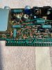
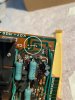
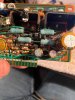
While in there, I noticed that a majority of the caps hadn't been changed, and that many of the larger caps are glued to the board with the notoriously bad brown corrosive glue. I also saw some of the PCB jumpers, as well as a couple resistors,
which were located near the glue, were starting to corrode slightly. I removed the resistors and measured them. They all measured fine, so I cleaned the leads and re-installed. I'm thinking about changing all of the suspect resistors in both amplifiers.

I currently have a large order coming from Mouser, including basically every cap in the amplifiers, excluding the large Elna filter caps, and the large 470uf 100v axial caps on the power boards. I also have both relays for each amplifier coming as well.

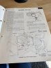
I recently was able to find the original service manual for the L-07M's on eBay, so I have been referencing it quite a bit. It goes into detail on how to separate the power supply section from the rest of the amplifier, and how to disassemble the whole thing
down to the frame. It's really quite handy. Kenwood/Trio seemed to have been very dedicated to making the disassembly of these amplifiers a walk in the park. Every part of these amplifiers is modular, except where some of the power supply board's wires are soldered to the main board.

I'm still waiting on the Mouser order, which should be here this Tuesday.

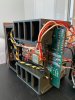
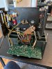
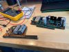
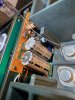
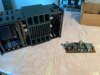
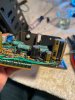
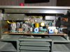
I'll include some pictures of the preliminary tear down that I took while gathering a parts list / inspecting the amps.

I'll also update this thread as I go along. I'm also open to suggestions on modifications and recommendations for these amplifiers as well. Thanks for reading along.

Connor
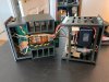
IMG_5262.JPG IMG_5266.JPG IMG_5269.jpg IMG_5264.JPG IMG_5271.JPG IMG_5263.JPG IMG_5284.JPG IMG_5265.JPG IMG_5267.JPG
 
Last edited:
Register to hide this ad
I'll be watching. I know when I got mine, I replaced a few corroded jumpers too. That glue really messes up components.
 
When I did a pair recently, I was so happy the transformer just unplugs and can be put somewhere else and you don't have to wrestle any part of the amp with it attached. Don't miss that one cap that is bipolar.
 
I'll be watching. I know when I got mine, I replaced a few corroded jumpers too. That glue really messes up components.
Fortunately, I could only see a few components that were affected by the glue. Should be an easy fix. They seemed to have been conservative with the glue in mine.
When I did a pair recently, I was so happy the transformer just unplugs and can be put somewhere else and you don't have to wrestle any part of the amp with it attached. Don't miss that one cap that is bipolar.
The service manual really helps out with disassembly. The removable power section is awesome. Makes everything so much easier. Thanks for the heads up about the bi-polar cap. While gathering a parts list, I managed to get it right. I have Elna Silmic II caps, as well as Nichicon audio grade caps coming.
 
Which big caps you using? I went up a bit on capacitance and voltage and they were tabbed but I had to open the slots a bit still plenty of trace to get a great soldered fitting.
 
Which big caps you using? I went up a bit on capacitance and voltage and they were tabbed but I had to open the slots a bit still plenty of trace to get a great soldered fitting.
I didn't opt to change out the filter caps, although I may. Thanks for the heads up on the board modification. Do you recall which caps you used? Thanks :)

found my old thread.
Hey rickl, Thanks for sharing that thread. I'll take a look!

Edit: How did you go about cleaning the old glue off? Looks like you did a good job.
 
How did you go about cleaning the old glue off? Looks like you did a good job.

I use lacquer thinner. it may take longer than acetone but I like the results. I use a plastic spudger to scrapped up the softened glue. You could also use a chop stick. I'd suggest not to use a screwdriver or metal scrapper.
 
Main cap. Difference in mounting is the originals have tabs centered and these have the rivets centered so the slots need to be enlarged but there is plenty of copper real estate to provide a full solder connection to the lug. A little more money than the typical PS caps.
LKG1K223MKZF
 
I use lacquer thinner. it may take longer than acetone but I like the results. I use a plastic spudger to scrapped up the softened glue. You could also use a chop stick. I'd suggest not to use a screwdriver or metal scrapper.
I have some plastic automotive scraping tools laying around. I'll give those a shot with some lacquer thinner. Thanks!

Main cap. Difference in mounting is the originals have tabs centered and these have the rivets centered so the slots need to be enlarged but there is plenty of copper real estate to provide a full solder connection to the lug. A little more money than the typical PS caps.
LKG1K223MKZF
I'll bookmark those for when I decide to change them out. Thanks again!
 
Parts came in today from mouser, so I got to work on one of the L-07M's .

I got pretty much done with everything on one of the monoblocks, just waiting on the speaker output relays, which were on backorder until the 25th. I'm also waiting for a couple more capacitors for the driver board.
I somehow ordered all the caps I needed, just 2 different versions of the same cap, so I have to order 2 more caps of the correct type, so both amplifiers will be the same.

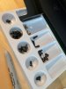
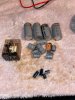
Here are the caps I used for one amplifier; The blue 100uf cap was not used as it one of two caps I ordered from the wrong series.
Also pictured is the replacement Omron power relay.

1.jpg

Here is a good shot of some of the corrosive brown glue, used to hold down certain capacitors.

2.JPG

Here is the same area, all cleaned up. I ended up going with @rickl's suggestion, slightly changed.
Instead of lacquer thinner, I used 90% isopropyl alcohol, along with plastic automotive scrapers. It worked great.

3.JPG

Driver board removed

4.jpg

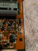
This is after cleaning the brown glue off of some capacitors on the driver board. I also cleaned much of the corrosion off of the jumpers, resistors, and diodes.
I measured all diodes and resistors out of circuit, and they all tested perfect. I may change suspect components in the future, but for now, they should be fine.

5.jpg

Same story here, I spent more time cleaning glue than I did actually replacing capacitors!

6.jpg

I ended up having to mount one of these 47uf capacitors off to one side, as there wasn't enough room to mount them together. That's what I get for neglecting to measure dimensional restrictions while upping voltage specs.
I made sure to insulate the legs, so they won't short out on nearby components. I think it turned out well.

7.jpg

Same capacitors, photo taken from the top. I tried to mount the capacitor on the right on it's side, but it prevented the board to be inserted into the adjacent board, because it was interfering with a transistor heat sink.
8.jpg

More photos to come, stay tuned.
 
Back plate removed. I was in the process of replacing capacitors and touching up solder joints on the main board.

9.JPG

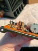
Photo of the driver board reinstalled into main board's socket. Capacitors on the far right were already replaced by my last tech, but I will be replacing them with Nichicon Fine Gold parts. They are the ones I managed to screw the order up on. Most of the caps my last tech used are Chinese no-names. Into the garbage they go.

11.jpg

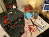
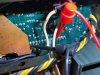
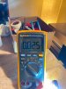
Offset adjustment. Managed to get it to 0mV +/-.2

12.JPG

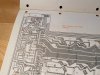
Bias adjustment test point locations on the schematic came in handy, I was struggling to find the test points called out, as most of the test points aren't labeled on the main board.

13.JPG

Test points acquired :cool:

14.JPG

Bias was 17mV when fully warmed up. Either my last tech misadjusted it, didn't bother to adjust it in the first place, or it drifted. Should have been 25mV.
Now it's right on.

15.JPG

Here are all of the parts changed today on one of the L-07M's. All that's missing is the 2 100uf caps that I'm still waiting on.
I also may put an order in for some new filter caps. I'll update with photos of the next monoblock when I get to it tomorrow.

16.JPG


:needpics:
 
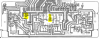
Missing these two capacitors on both amplifier boards. Both amplifiers have been working without them. Anyone know if this should be like this?
upload_2020-3-18_15-28-4.png
 
Looking at other pictures of the main board online, it seems like these two capacitors are absent as well.

upload_2020-3-18_15-34-33.png

Here is a photo of mine:

upload_2020-3-18_15-35-4.png
 
Back
Top Bottom