• The move to the new server is done. There are some software and database maintenance updates in process. This has us passing the hat around to help out. We appreciate any donations. Seriously, even a dollar helps. The payment page may be found here - https://www.audiokarma.org/support.html

Kit or parts selection for Fisher 500B

Allright, finally gettin' 'round start installing the parts...

Tuner 1uf 400v and 10uf 50v
IMG_0637.JPG

IMG_0638.JPG

Screen Resistors

a. resistors go from pin 1 to 4 and marked in green
b. wires tying pin 1s together marked in red
c. lead moved from v13 pin 8 to r133 marked in blue
d. r133 marked in yellow
e. the bridges between pin 4 and 8 between tubes was removed

Please let me know what mistakes I may have made or forgotten to do here.

IMG_0639.JPG

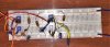
Also, starting to build the ibba and would like to test it out on a breadboard using jumpers to the appropriate points on the unit before making permanent wiring.

I've labeled these per the schematic in post #12 here: http://www.audiokarma.org/forums/in...dividual-bias-adjustment-modification.601583/

IMG_0643.JPG

Some questions:

1. Is the picture above enough for anyone to verity that I got the wiring right? If not, let me know any questions or if I can take better pictures.
2. I've marked A, B, C, D per the schematic. Where should these attach on the 500b?
3. Where to I attach to the -25v heater supply in the 500b? (Is this point V on the 500b schematic, image below)
4. I assume I can wire ground to the chassis with a screw and locking washer?
5. Do the test points connect to pin 5 of the output tubes?
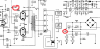
point v.png
 
Assuming that for the "ABCD" leads, that they connect as follows:

I would break the connection b/w the resistors at the points in red/ Each resistor end would then connect to A,B,C,D as shown below in the 500b schematic.

6. Is that correct?


abcd.png
 
Last edited:
While awaiting confirmation of the IBBA wiring above, I did start the unit up with the old tubes just to make sure the wiring is OK before adding in another change.

Seems like it's OK. One more newby question on the thermistor for current inrush protection.

7. The McShane kit came with .01uf 1600V caps for C91 and C92 and these have been put into place. Would I replace one of these capacitors with the CL80? If so, which one? C92?
8. Would there be any advantage to having both a thermistor and replacement cap in line?
 
Post 43. CORRECT. Remove the "V" section all the way back to the dual caps. You can use this to power the IBBA or IBAM. Split the 220K so they have a free end and connect the IBBA wiring one pot to each 220K resistor. Tie in the power from the wire you removed from "V" that is still attached to the dual caps, and run your gnd line to the closest convenient ground lug on the chassis.
ScreenHunter_315 Jun. 13 21.42.jpg

Previous post.
7 )NO Neither one.
8.) The thermistor and the caps do different jobs. Install the CL-80 between the power cord and the switched side of the primary (opposite side from C-92). Leave C91 & C92 in and alone once you install the new replacements..
 
Last edited:
Thanks Larry!

As a double check with the experts..

The red arrows show which ends of the grid resistors get removed and wired to a/b/c/d of the IBBA. (d is hidden under r133)
The red x is a wire bridging the grid resistors and will be removed.
The blue arrows are the test points.
The yellow arrow shows where the white wire coming from point "V" on the schematic. (hidden under red/white wire and coming from where 5.6K resistor and 100uf cap meet)
The green where I'm thinking to ground.

ibba plan.jpg

And CL80 Here: Better to attach to the line coming in (in blue) or the wire leaving that terminal to the switch (green arrow)?

cl80.jpg
 
Last edited:
And for the removal of r129, r135 and c85.

Remove items with Red x's
Green Arrow shows white wire to grid resistors ("V" or -25) which will now connect to IBBA -25 connection.

Blue shows wire I'll have to run to recomplete circuit to connect white wire to where negative terminals of C79A and C79B meet. Or, the lowest resistor in the picture below can be replaced with a wire.(Because the old can was left in place to allow several of the connections to remain without extending wires)

Does that look / seem right for the removal of the 'vestigial' parts?

IMG_0655.JPG
 
Last edited:
Just remove the 2 resistors and the one cap, and run a jumper to where you have it marked. Probably best to use left over from the white wire after fitting in the IBBA board. The other feed on that terminal is for the 4 tube heaters for the voltage amp tubes and the phono tubes.

Take the Blue marked wire off the terminal and solder one leg of the CL-80 to it, and the other end to the terminal strip at the green marked wire. Make sure it has plenty of room around it as it gets blistering hot. It will remove your fingerprint's!
 
Thank again Larry. One final question before I begin the soldering.

I am not very good at reading schematics and had some questions on wiring the pots.

I've poorly copied dcgillerpies excellent diagram and labeled what I think are the right pins for the balance and bias pots. This would be so that clockwise movements of the pots (bias) will increase current.

image.jpeg
Does the above look right? I've labeled the pins 1,2,3 as appropriate and tables listing what's connected to the various pins.

Reading up on pots assuming that the bias pots are acting as variable resistors and control current and the balance pots as voltage dividers?

Sam
 
On the bias pots, connect the center (#2) to one of the outer pins, either #3 or #1. Then with an ohm meter connected to the outer pins, determine minimum ohms. That is your MAXIMUM VOLTAGE to the tubes (approx -25v or what ever you are getting from the caps). This should be max counterclockwise. As you turn clockwise the pot is acting as a resistor starving off voltage to the tubes (it will drop toward ZERO). If it's max clockwise just move the wiper (#2) to the opposite outer pin.
Then connect to the wiper of the balance pot.
 
Finally made some time to get back to this inspite of the long work hours during the week and the too good not to be outside weather on the weekends!

Did get the inrush protection in place and r129, r135 and c85 removed.

cl80 (2).JPG

resist removal.JPG

I am not totally 100% I completely follow on the pots wiring, but I've loosely put the parts into the perf board and here's how I plan to physically wire on the back. The part I'm particularly confused about is the bias pots and balance pots. I've color coded for ease of commentary, so hope this helps.

ibba on perfboard ver 1.jpg

Below is the schematic image from dcgillespie that he posted in his thread where I am trying to copy the work and instructions. Here's that thread http://audiokarma.org/forums/index....dividual-bias-adjustment-modification.601583/

dc gillespies.jpg

Questions

1. Are the bias and balance pots in the color coded photo wired correctly? (particularly the bias pots)

2. Any problem with using 18/5 solid copper core thermostat wire? I bought some 22ga wire from Mouser, but it's a black spool, and I thought the heavier gage and color coding would be better here.

3. Open to any suggestions for wiring this better or more efficiently. (For instance I'm thinking that it might be better to wire the 15k wires in reverse of what's shown as they all need to merge and go to the -25v supply. i.e. switch which side of the resistor the violet and red lines go to. Would appreciate any help in getting less 'spaghetti' on the back of the board)
 
Last edited:
Here's a cleaner attempt. Will go ahead and give this a try unless there's any reason not to.

ibba version 2.jpg

Will post results shortly.
 
It's been a while, but finally got this done several weeks ago. Pretty happy with the results and all functions working. I couldn't dial the bias below ~36 so just matched them all at 37.

Here's the IBBA. Just stuck it to the chassis with double sided tape. You might notice that the 1st tube is shorter than the next. This was the oddball, and the other 3 are the same height. These were a matched set electronically though, so it doesn't bother me a bit.

ibba.JPG

View from front, and you can see the ibba at the back of the chassis between the transformers and the cap cans.

after.JPG
 
Back
Top Bottom